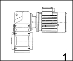
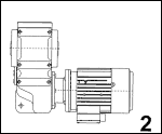
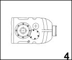
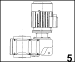
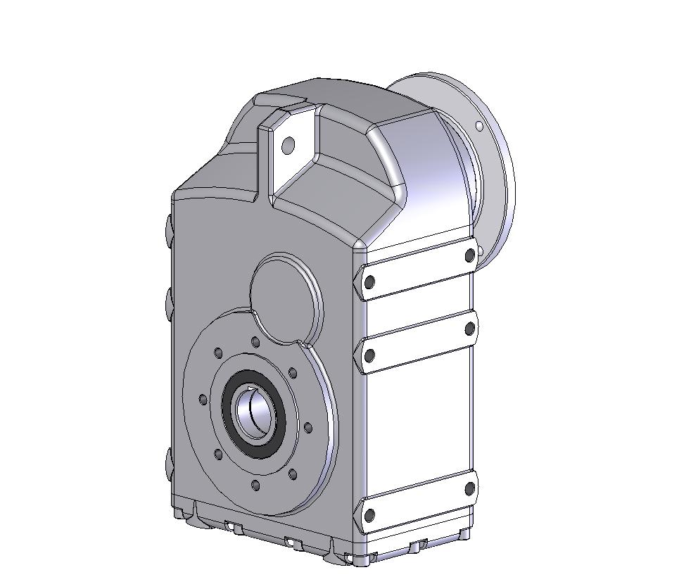
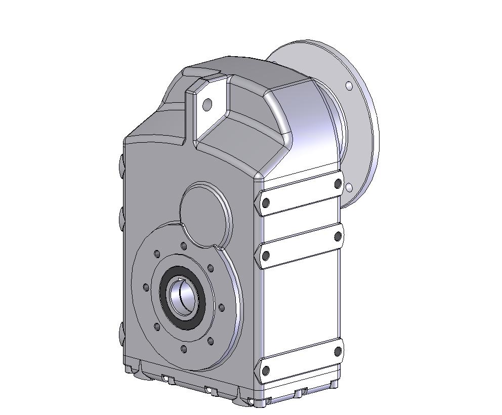
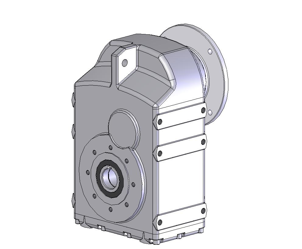
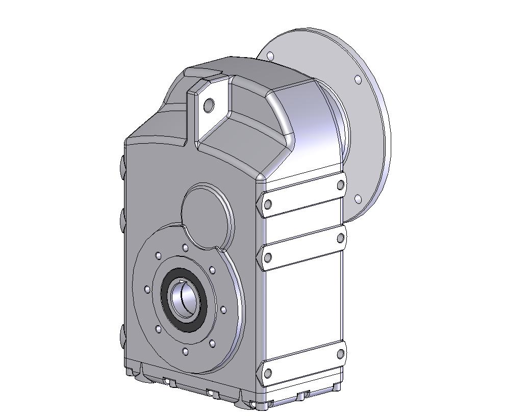
Spur gearboxes TNC
Size: 1 ÷ 6
Gear ratio: „i“ = 4,4 – 180
Power: 0,18 – 45 kW
Torque: 16 – 5500 Nm
Information about product
Specialized manufacturer of gearboxes and variable speed gearboxes offer a range of spur gearboxes. Their dimensions and power outputs provide wide application of these gearboxes. High quality materials and traditional accuracy of production as well as carefulness of mounting provide long service life and operation reliability of product.
Concept
Proper concept of spur gearboxes designed by the manufacturer´s designing department was made by computers and special software. Drawings and accompanying documents have also been made by CAD – Computer-aided-design. Thus the product has correct dimensions and parameters of operation.
Compact feature
Integrated gearing makes it possible to reduce dimensions of the gearbox. High accuracy of machining of gears reduces vibrations and provides noiseless running.
Continuous change of speed
The manufacturer provides TNC gearboxes with frequency inverters SIEMENS.
Adaptation to customer´s requirements
Great amount of combinations of input and output shafts and flanges enables to use TOS gearboxes almost for all required types of drives.
Variability
The gearbox shape makes it possible to attach the gearbox to all types of devices.
Fine gear ratio spacing
Adjustment of gears and their fine spacing from i = 4.4 makes it possible to choose precisely the output speed.
Motors
The gearboxes can be equipped with different types of motors.
Surface protection
The gearboxes are painted with priming coat and sprayed with polyurethane paint. Paint of TNC gearboxes matches with the paint of motor.
Lubrication
Train of gears is oil-lubricated. Quantity of oil is shown in chapter LUBRICATION.
Type identification of product
The gearbox is determined by the Type marking. Therefore, an order should state complete code number as shown below.
The order should also contain an order form shown in chapter 13 in which the customer can specify different requirements.

a) Type:
TNC marking of flat gearboxes with hollow shaft manufactured in TOS ZNOJMO.
b) Designation:
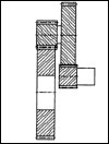
it is given by size 1 – 5, Tab. 2.1 and number of speed gears as shown in Tab. 6.1.
Table 2.1.
| Size | Two-stage gearboxes (TNC _2) | Three-stage gearboxes (TNC _3) | Ø of hollow output shaft | ||
|---|---|---|---|---|---|
 |
marking | 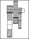 |
marking | ||
| TNC 1_ | 1 2 | 1 3 | 30 | ||
| TNC 2_ | 2 2 | 2 3 | 35 | ||
| TNC 3_ | 3 2 | 3 3 | 40 | ||
| TNC 4_ | 4 2 | 4 3 | 50 | ||
| TNC 5_ | 5 2 | 5 3 | 60 | ||
| TNC 6_ | 6 2 | 6 3 | 70 | ||
c) Position of box:
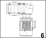
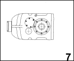
The shape and design of gearbox make it possible to use the gearbox under various operation positions as shown in Tab. 2.2. The position is given by code numbers 1-7.
Table 2.2
d) Input design:
- pin
- with mounted electric motor
- without mounted electric motor with flange IM 3641 FT** (IM B14 FT** ) – smaller flange B14 A
- without mounted electric motor with flange IM 3641 FT** (IM B14 FT** ) – greater flange B14 B
- without mounted electric motor with flange IM 3041 (IM B5)
e) Output design:
- output without fastening flange
- output with flange, as shown in table 7.1.
Ratio i: according to individual Types specified in table of power outputs
Type of electric motor and its power output P1: see table 8.1 ; or electric motor output P1 as shown in table 6.1.(power parameters)
Example of Type identifikation
| a) flat gearbox | ….. TNC X X X X X |
| b) gearboxsize 3 | ….. TNC 3 X X X X |
| c) two-stage gearing | ….. TNC 3 2 X X X |
| d) horizontal position of shaft axis, motor up | ….. TNC 3 2 1 X X |
| e) with electric motor | ….. TNC 3 2 1 2 X |
| f) without fastening flange on output | ….. TNC 3 2 1 2 1 |
| g) ratio | ……………..i = 11,4 |
| h) Type of electric motor and power output: Type 90L, 4-pole, output 1.5 kW | …. 90L 4, 1,5 kW |
Additional requirements should be stated in the order form.
Correct parameters of gearbox could be verified according to chapter 4 – design of gearbox size.
Assembly
The spur gearboxes are supplied in TNC design with hollow input shaft modified for assembly of electric motors according to IEC.
When TNC design without mounted motor is required, the order form should state the diameter of electric motor shaft and flange dimensions as well (diameter of pitch circle of fastening holes). When choosing an electric motor, the user is directed to chapter „Electric motors“ where he could find combinations of power output, speed, height of axis by IEC and other values of electric motors. Detailed information about electric motors can be obtained from a catalogue of electric motors manufacturer.
Rated powers
Shown in the below table are maximum values of power outputs and corresponding values of output torque which the gearboxes are able to transmit. These values are determined for uniform load of gearbox without shocks – for operation factor Sm = 1, and rated speed n1 = 1400 min-1.
Power parameters
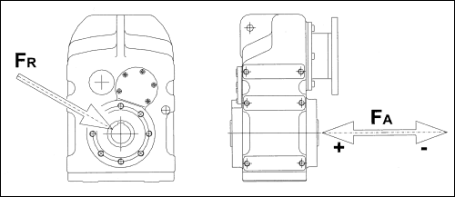
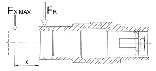
Gearboxes in the table are arranged according to driving electric motor. Corresponding output speed n2, output torque M2, service factor Sf and admissible radial load of hollow output shaft Fr are determined for rated power and electric motor speed n1 = 1400 r.p.m.
Table 6.1. Tables of power parameters TNC
power P1[kW]
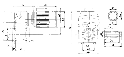
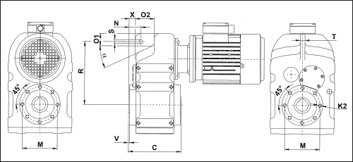
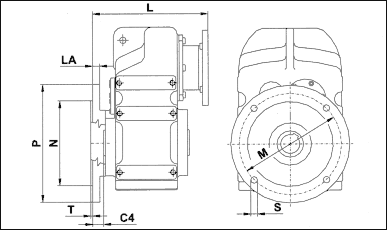
Dimensional data (mm)
Dimensional drawings gives dimensions of transmissions boxes in basic design. Under your request may be your transmission boxes delivered in special design.
Electric motors
This chapter deals with basic technical data and dimensions of motors of an axial height of 56 up to 160 that are delivered by electric motors manufacturer Siemens Electric motors s.r.o. Mohelnice (http://www.siemens.cz). If additional or detailed technical information is required then ask the manufacturer for a special catalogue of motors.
Lubrication
Lubrication of gearing and bearings is indispensable for reliable function of gearbox throughout its service life. Correct lubrication provides high efficiency and noiseless running, and substantially decreases the box wear. TNC gearboxes are once for ever filled with high-quality synthetic oil. Therefor the boxes have no filling, check a draining holes. Quantity of lubricant for individual size of gearbox is shown in table 10.1.
Table. 10.1
| size | TNC 1_ | TNC 2_ | TNC 3_ | TNC 4_ | TNC 5_ | TNC 6_ |
|---|---|---|---|---|---|---|
| quantity of lubricant [l] | 0,7 | 1,2 | 2,2 | 3,0 | 7,5 | 17,0 |
We recommend to use our standard synthetic lubricants but its also possible to use mineral oils. Suitable lubricants (equal equivalents of various manufacturers) are shown in table 10.2.
| Lubricant | mineral oils | synthetic oils | ||
|---|---|---|---|---|
| Ambient temperature | -10 oC – +50 oC | -10 oC – +50 oC | ||
| Type of load | normal | heavy | normal | heavy |
| Agip | Blasia 220 | Blasia 320 | Blasia S | |
| Aral | Degol BG 220 | Degol BG 320 | Degol GS 220 | |
| Castrol | Alpha SP 220 | Alpha SP 320 | Alpha SH 220 | |
| ESSO | Spartan EP 220 | Spartan EP 320 | ||
| Klüber | Lamora 220 | Lamora 320 | Syntheco HT 220 | |
| Mobil | Mobilgear 632 | Mobilgear 634 | SHC 630 | |
| Shell | Omala EP 220 | Omala EP 320 | Omala HD 220 | |
| OMV | Ole HST 220 EP | Ole HST 320 EP | Unigear S 75 W-90 | |
| Optimol | Optigear BM 220 | Optigear BM 320 | Optigear A 220 | |
| Total | Carter EP 220 | Carter EP 320 | ||
| Paramo | Paramol CLP 220 | Paramol CLP 320 | ||
Mineral oils of a viscosity class of ISO-VG 220 are introduced for medium and lighter operation conditions and lower temperature; viscosity class of ISO-VG 320 is used for heavy operation and higher ambient temperature.
Mineral oil charge is replaced after first 400 hours of operation and then after every 4000 hours of operation.
Warning !
Never mix synthetic and mineral lubricants ! Mixing of synthetic products of various manufacturers may cause troubles. When changing type or mark of lubricant the gearbox should be perfectly cleaned.
Accessories
Shaft couplings
At customer´s special request the TNC gearboxes can be equipped on output (or input) with suitable type of shaft coupling to adjust radial, axial and angular offset of shaft, with slipping clutch to limit the transmitted torque, or with a free wheel, or with a combination of flexible coupling with slipping clutch and flexible coupling with free wheel.
Storage, putting into operation, maintenance
Storage
The manufacturer protects external function surface against atmospheric corrosion with a preservation spray. If the gearbox is to be stored or put out of operation for a long time, it is necessary to renew protection depending on the surrounding. In case of long-term storage the gearbox should be refilled with oil as mentioned in chapter „lubrication“.
The gearbox should be stored in dustless and dry area. Temperature of storing area is to be from 0 to 40oC. We recommend to move the output shaft through at least one turn once in 3-4 months.
gearboxes should be transported and stored in assembled position.
Installation, putting into operation
When installing the spur gearbox:
- make sure that there are no external vibrations and high ambient temperature in the area, remove any obstructions that may hinder air and heat flow near the gearbox;
- to avoid damage to the spur gearbox, see that protective switches and couplings are used in case of impact-loads;
- see that connected shafts are aligned and couplings mounted according to the supplier´s directions for use;
- see that holes of parts at the output shaft end are made in a tolerance of H7 and lockled with splines;
- see that the gearbox is mounted on a plane machined surface;
- see that thread-mounted components on the shaft front side are secured against loosening;
- protect gearboxes against sun and adverse weather;
- check the oil level and top up if necessary.
Shaft gasket
Correct function and faultless condition of shaft gasket provide faultless operation of gearbox. Service life of gasket is influenced by ambient temperature and chemical reactions that may arise between materials of gasket and lubricant.
Replace the shaft gasket in case of its damage or improper function.
Spare parts
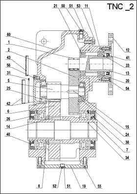
To specify any spare part, it is also necessary to mention the data from the rating plate.
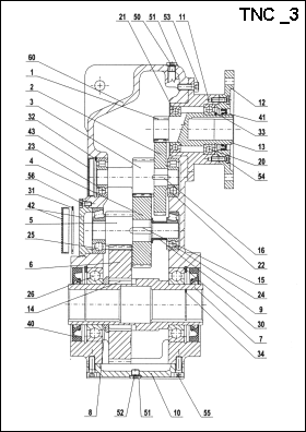
| 1 | pinion | 11 | reduction gear | 24 | bearing | 42 | lid |
|---|---|---|---|---|---|---|---|
| 2 | gear I | 12 | flange | 25 | bearing | 43 | lid |
| 3 | shaft with pinion II | 13 | coupling | 26 | bearing | 50 | vent plug |
| 4 | gear II | 14 | key | 30 | retaining ring | 51 | plug |
| 5 | shaft with pinion III | 15 | key | 31 | retaining ring | 52 | gasket |
| 6 | gear III | 16 | key | 32 | retaining ring | 53 | bolt |
| 7 | output hollow shaft | 20 | bearing | 33 | retaining ring | 54 | bolt |
| 8 | spacing ring | 21 | bearing | 34 | retaining ring | 55 | bolt |
| 9 | ring | 22 | bearing | 40 | shaft gasket | 56 | bolt |
| 10 | box cover | 23 | bearing | 41 | shaft gasket | 60 | transmission box |
Photogallery
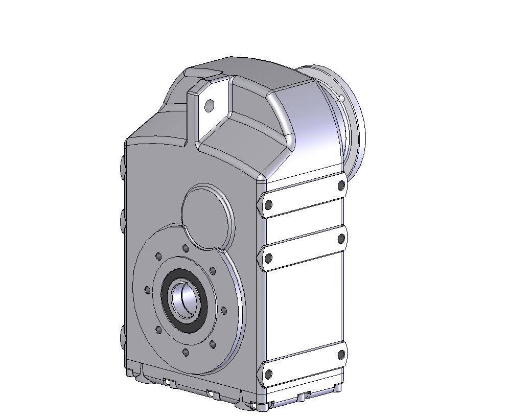
Výkresy a 3D modely
Výkresy převodovek TNC63
| Převodovka TNC63, Dutá hřídel, příruba motoru M=215, motor IEC 100 | ||
|---|---|---|
| tnc63-f215-ap100.dwb | tnc63-f215-ap100.exe |
| tnc63-f215-ap100.dwg | tnc63-f215-ap100.step.zip | |
| tnc63-f215-ap100.dxf | tnc63-f215-ap100.sldprt | |
| Převodovka TNC63, Dutá hřídel, příruba motoru M=265, motor IEC 132 | ||
| tnc63-f265-ap132.dwb | tnc63-f265-ap132.exe |
| tnc63-f265-ap132.dwg | tnc63-f265-ap132.step.zip | |
| tnc63-f265-ap132.dxf | tnc63-f265-ap132.sldprt | |
| Převodovka TNC63, Dutá hřídel, příruba motoru M=300, motor IEC 160 | ||
| tnc63-f300-ap160.dwb | tnc63-f300-ap160.exe |
| tnc63-f300-ap160.dwg | tnc63-f300-ap160.step.zip | |
| tnc63-f300-ap160.dxf | tnc63-f300-ap160.sldprt | |
| Převodovka TNC63, Dutá hřídel, příruba motoru M=300, motor IEC 180 | ||
| tnc63-f300-ap180.dwb | tnc63-f300-ap180.exe |
| tnc63-f300-ap180.dwg | tnc63-f300-ap180.step.zip | |
| tnc63-f300-ap180.dxf | tnc63-f300-ap180.sldprt | |
| Převodovka TNC63, Dutá hřídel, příruba motoru M=350, motor IEC 200 | ||
| tnc63-f350-ap200.dwb | tnc63-f350-ap200.exe |
| tnc63-f350-ap200.dwg | tnc63-f350-ap200.step.zip | |
| tnc63-f350-ap200.dxf | tnc63-f350-ap200.sldprt | |


