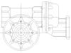
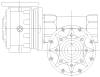
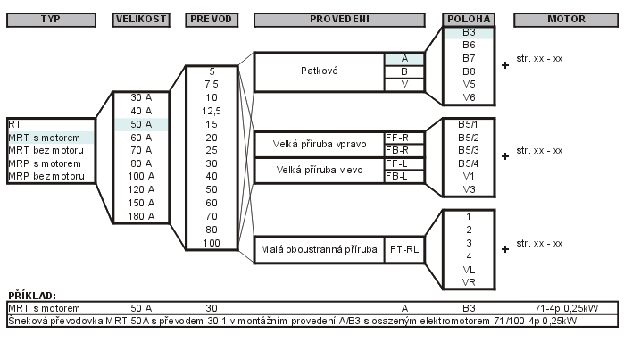
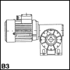
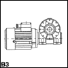
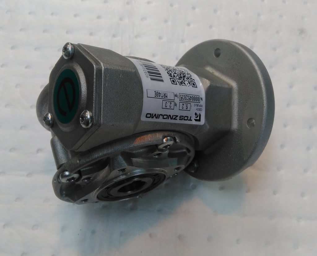
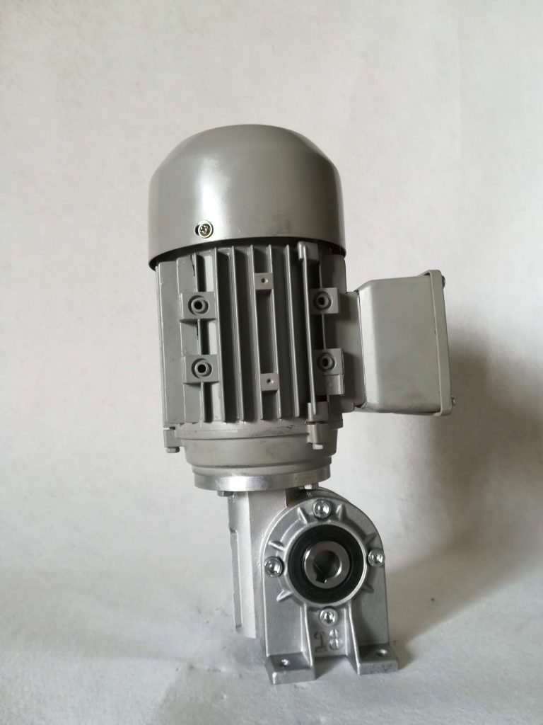
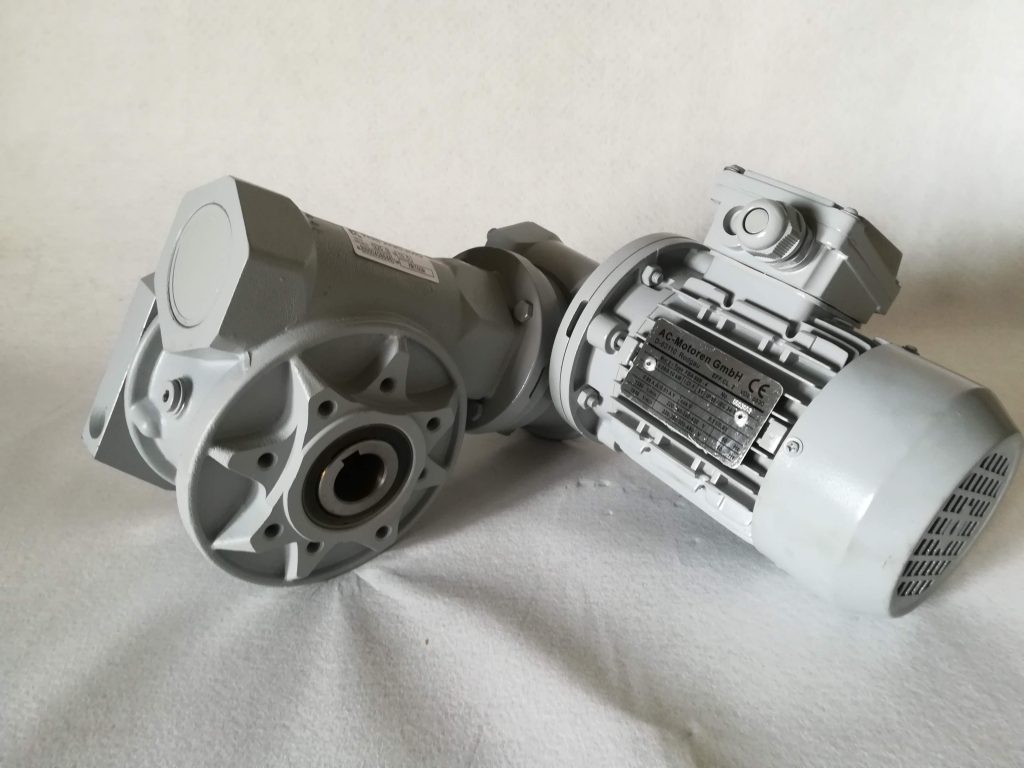
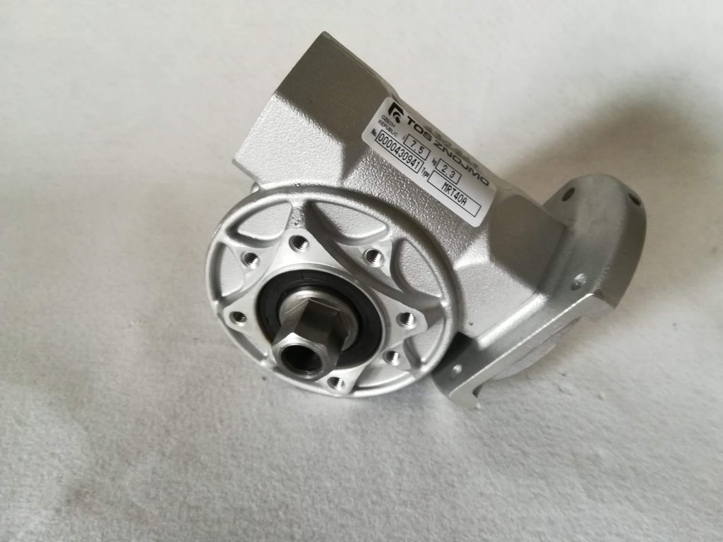
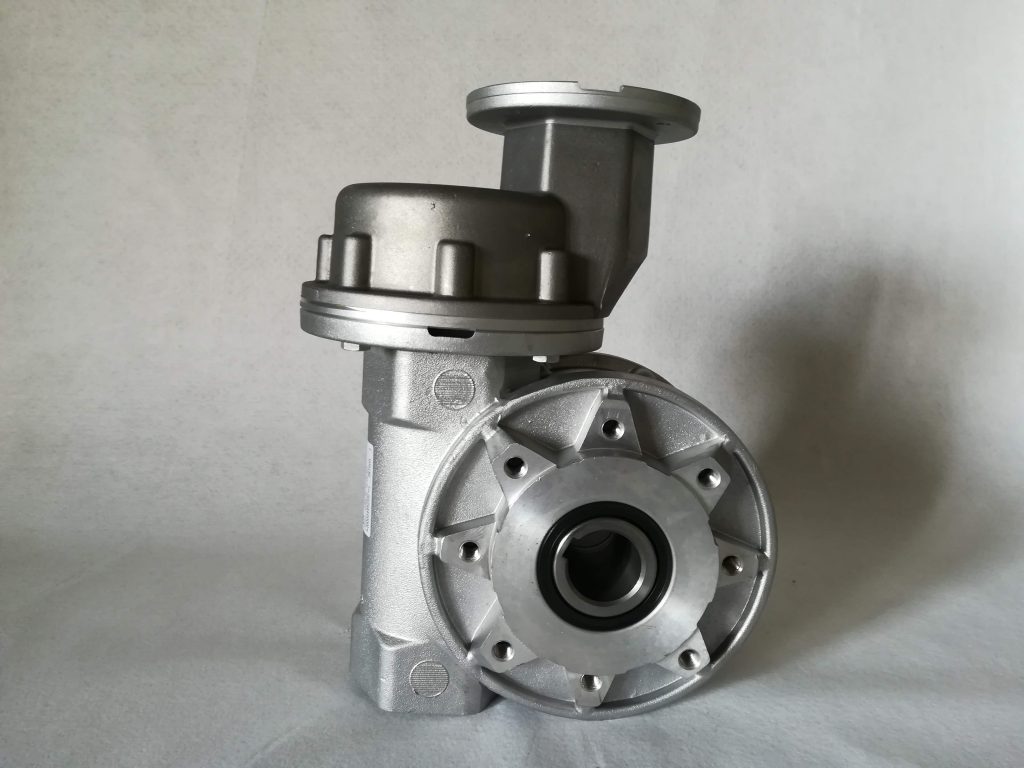
Worm gear reducers RT/MRT
Size : 28, 30, 40, 50, 60, 70, 80, 100, 120, 150, 180
Transmission ratio : „i“ = 5 – 100
Power: 0,06 – 15 kW
Torque: 8 – 2540 Nm
General design
Modern design, proved quality, reliability and the involute gear profile used at the worm gearing guarantee trouble-free service of RT / MRT . . A, series gear unites manufactured by TOS ZNOJMO. The RT/MRT30A to RT/MRT80A gear unit housings, feet and flanges are made of aluminium alloy and are supplied unpainted as standard. The RT/MRT100A to RT/MRT180A gear units housings are of cast iron and are supplied RAL5021 green-blue painted. By request any worm-gear unit can be supplied in stainless steel execution.
Characteristic properties of worm-gear units:
- High gear ratio 5 to 100 achieved by one gear unit only
- Noise-free operation
- High load capacity
- Self-locking ability
- Reduced weight
- Easy integration to the driven machine
Identification of basic design
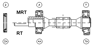
| RT . . | Worm-gear unit with the solid input shaft |  |
| MRT . . | Worm-gear unit with an electric motor or with hollow
input shaft fitted with a flange for B5 mounted electric motor or B14A mounted motor or B14B mounted motor |
 |
| MRP . . | Worm-gear unit with spur gear step (i = 3) at the input shaft |  |
| MAT . . | MRT worm-gear unit with ATC in-line gearbox at the input shaft
( i = 3,4 and/or i = 6, and/or i = 8 |
 |
| MRT . . x . . | Combination of two worm-gear units to achieve very high gear ratios
i = 4,000. Gearbox combinations up to i = 10,000 ratio are available as an option. |
 |
Selection
General
The wide range of ratios specified in the catalogue enables to solve any requirements resulting from the operation of various equipment. The following data are necessary to specify a suitable gear unit:
a) input and output speed determining the gear ratio i
b) required torque Mk, or input power P1
The data given in the tables 8.1 až 8.4, enable easy selection of a suitable gear unit. Should a non-standard unit be required please contact your distributors for the technical support.
Gear Ratio i
Gear ratio is a relation between input speed n1 [rpm] and output speed n2 [rpm].
n1
i = ———————
n2
Gear ratios from 5 to 100 are used at worm-gear units. The use of squirrel cage asynchronous motors is recommended to drive the equipment as their speed n1 [rpm] is almost constant even if under load. The following speed can be used for 50 Hz:
- 2 – pole motor n1=2800 rpm
- 4 – pole motor n1=1400 rpm
- 6 – pole motor n1=900 rpm
- 8 – pole motor n1=700 rpm
Two-pole motors are usually suitable for short-time operation.. It is, however, possible to use these after consultation with the manufacturer. Their use should be consulted with the manufacturers. When 60 Hz supply frequency is used the increase of the input as well as output speed by 20 % need to be taken into consideration.
Torque M2
The required torque Mk is determined by the load applied on the gear unit. It can be described as force F applied at certain distance of the arm r.
Mk[Nm] = F[N] x r[m]
The output torque M2 can be calculated from the following formula:
9550 x P1[kW] x η[%] x i
M2[Nm] = —————————————–
100 x n1[rpm]
The output torque M2 is selected greater than the desired torque. 2 need to be selected at a higher value than the required torque. Output torque related to individual gear ratios is specified in the Gear Unit Selection 8.4.
Input and Output Power P1 and P2
Motor input power can be calculated from the general relation between torque M and speed n :
M[Nm] x n[rpm]
P[kW] = —————————-
9550
The efficiency  , of a gear unit is given by the ratio of the output power P2 and the input power P1, see Table 8.1 to 8.3.
Mkrequired [Nm] x n2[rpm]
P1[kW] = —————————————————-
9550 x [%]
Service Factors
Operation factor Sm
In order to guarantee operation safety at various loads and operation conditions the type of the gearbox (and motor) must be specified through the operation factor Sm. The values of operation factor Sm can be found in Table 6.1 taking the type of load, the average daily operation, the number of starts per hour into consideration. These values are applicable when the gear unit is used in conjunction with an electric motor. Should a brake motor be used the operation factor Sm needs to be multiplied by a coefficient of 1.15. When selecting an actual gear unit the operation factor Sm must be lower than the gear unit service factor Sf or the required output torque Mp must be increased as per the following formula:
M2 = Mp x Sm
Tab. 6.1 Service Factors
| Kind of load | Number of starts per hour | Average daily operation [hr] | |||
|---|---|---|---|---|---|
| <2 | 2÷8 | 9÷16 | 17÷24 | ||
| Normal shock-free operation, small inertia (fans, gear pumps, assembly lines, conveyer screws, liquid mixers, filling machines and wrapping machines) |
<10 | 0,8 | 1 | 1,2 | 1,3 |
| Light jolts at starting, irregular operation, medium inertia (conveyer belts, hoists, winches, kneading and mixing machines, woodworking machines, printing machines,textile machines) |
<10 | 1,0 | 1,3 | 1,5 | 1,6 |
| 10÷50 | 1,2 | 1,4 | 1,7 | 1,9 | |
| 50÷100 | 1,3 | 1,6 | 2,0 | 2,1 | |
| 100÷200 | 1,5 | 1,9 | 2,3 | 2,4 | |
| Heavy shock irregular operation, high inertia (concrete mixers, suction pumps,
compressors, rams, rolling mills, heavy goods conveyer belts, bending machines, presses, machines with irregular load and motion) |
<10 | 1,2 | 1,5 | 1,8 | 2,0 |
| 10÷50 | 1,4 | 1,7 | 2,1 | 2,2 | |
| 50÷100 | 1,6 | 2,0 | 2,3 | 2,5 | |
| 100÷200 | 1,8 | 2,3 | 2,7 | 2,9 | |
Service factor Sf
Service factor Sf is a ratio between the maximum output torque the gearbox can continuously develop and the actual output torque which can be developed by the selected electric motor.
M2max
Sf = ————————— [ – ]
M2
The maximum torque M2max is established for the operation factor Sm = 1. Service factor values for individual gearbox executions and sizes, the gear ratios and a selection of electric motors are shown in the Table 8.4
Reversibility and parameters
Reversibility
A worm gearing is self-locking if it is not possible to turn the input shaft by turning of the output shaft. The worm gearing is self-locking if the worm helix angle is lower than the friction angle at idle or when the static efficiency of the gearing is lower than 50 %. The gearing is then statically self-locking. Should the worm helix angle be lower than dynamic friction angle or when the dynamic efficiency of the gearing is lower than 50 %, the gearing is dynamically self-locking.
The following relation applies:
 = tg
= tg / tg(+
 ) or = tg / tg( + arctg(
  z))
z))
… efficiency
… worm helix angle
… friction angle ( =arctg(z))
z … coefficient of friction in gearing
Static coefficient of friction between gear materials (steel – bronze) is within the range of z = 0.09 to 0.14 depending on the lubricant used (its age, conditions and temperature) and the roughness of contact surfaces (given by gearing wear). The conforming friction angle is s = 5° to 8°.
When static self-locking property can be influenced by vibrations or shocks a dynamic coefficient of friction shall be considered. The value of the dynamic coefficient of friction depends on surface roughness, the lubricant used, the load applied and the sliding speed. It ranges within z = 0.02 and 0.05 for standard load and speed 900 to 1400 rpm. The conforming dynamic friction angle is d = 1° to 3°.
With respect to the fact that the helix angles are higher than 1,5° at all gear ratios, the 100% self-locking cannot be guaranteed. In cases when the gear unit must be secured against slipping, it is recommended to use electric motors with brakes.
Tab. 16.2. Self-locking Status
| γ | Self-locking |
|---|---|
| >25° | total reversibility |
| 12° – 25° | static reversibility |
| reversing rapidly | |
| dynamic reversibility | |
| 8° – 12° | variable and static reversibility |
| reversing rapidly when vibrating | |
| dynamic reversibility | |
| 5° – 8° | static self-locking |
| reversing when vibrating | |
| light dynamic self-locking | |
| 3° – 5° | static self-locking |
| reversing slowly when vibrating | |
| almost dynamically self-locking | |
| light dynamic reversibility when vibrating | |
| 1° – 3°
<1° |
static self-locking |
| dynamic self-locking | |
| light dynamic reversibility when vibrating | |
| full static and dynamic self-locking |
Table of actual transfers
| MRT30A | MRT40A | MRT50A | |||||||
| iN | z2 | z1 | iR | z2 | z1 | iR | z2 | z1 | iR |
| 5 | 29 | 6 | 4,833 | 26 | 5 | 5,2 | 30 | 6 | 5 |
| 7,5 | 30 | 4 | 7,5 | 31 | 4 | 7,75 | 31 | 4 | 7,75 |
| 10 | 29 | 3 | 9,667 | 29 | 3 | 9,6667 | 29 | 3 | 9,6667 |
| 12,5 | 37 | 3 | 12,33 | 37 | 3 | 12,333 | 38 | 3 | 12,667 |
| 15 | 31 | 2 | 15,5 | 29 | 2 | 14,5 | 31 | 2 | 15,5 |
| 20 | 39 | 2 | 19,5 | 39 | 2 | 19,5 | 40 | 2 | 20 |
| 25 | 25 | 1 | 25 | 51 | 2 | 25,5 | 51 | 2 | 25,5 |
| 30 | 30 | 1 | 30 | 30 | 1 | 30 | 30 | 1 | 30 |
| 40 | 40 | 1 | 40 | 40 | 1 | 40 | 40 | 1 | 40 |
| 50 | 50 | 1 | 50 | 50 | 1 | 50 | 50 | 1 | 50 |
| 60 | 60 | 1 | 60 | 60 | 1 | 60 | 60 | 1 | 60 |
| 70 | 70 | 1 | 70 | 70 | 1 | 70 | 70 | 1 | 70 |
| 80 | 80 | 1 | 80 | 80 | 1 | 80 | 80 | 1 | 80 |
| 100 | 100 | 1 | 100 | 100 | 1 | 100 | 100 | 1 | 100 |
RADIAL AND AXIAL SHAFT LOADS
Worm-gear units are supplied with a hollow output shaft where a solid output shaft can be inserted. The robust housing of the hollow shaft and its bearings enable absorption of high radial forces while its service life is comparable with the other gearbox parts. The values shown in the Table 7.1have been calculated for the input speed of 1400 rpm. The maximum applied load shown 7.1 must not be exceeded. Taper bearings can be used on the output shaft at sizes 40 to 150 if required. A use of different bearings at the gear units need to be consulted with the manufacturers.
Radial Load Frad
To establish the radial load Frad the middle of the solid inserted shaft length is considered to be the point where the force is applied (see Fig.7.1). Should the actual radial load be applied on the shaft at a greater length, the maximum load must be reduced. For example only 80 % of the radial load shown in the table is applicable should the force be applied at 75 % of the shaft length. The radial load higher by 25 % can be applied should the force be applicable at 30 % of the shaft length. If a pulley, chain sprocket or gear wheel, etc. is fitted on the output shaft, the radial load can be determined from the following formula:
M2 x k x 2000
Frad = ——————————
D
| Frad | = | radial load [N] |
| M2 | = | output torque [Nm] |
| D | = | calculated pulley diameter (pitch circle) [mm] |
| k | = | load factory 1,00 for chain sprockets 1,25 for spur gears wheels 1,50 for pulleys |
It means that the shaft radial load can be decreased by the increase of the pulley diameter, if at all possible. Should the radial load be too high or the force be applied on the shaft at a long distance, an external support by bearings must be opted for to the force be applied on the shaft at a long distance, an external support by bearings must be opted for to absorb the additional forces.
Axial load Fax
Permissible values of axial load Fax represent approximately 20 % of permissible radial load Frad.
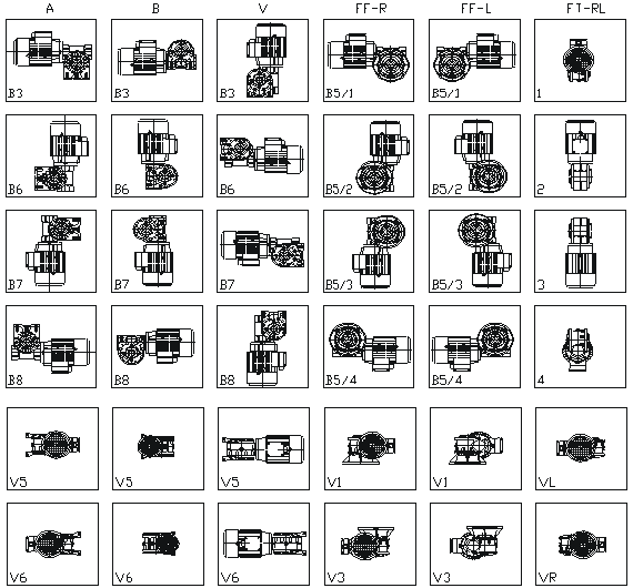
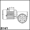
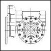
TYPE IDENTIFICATION DIAGRAM
Nominal Power
In operating conditions with a service factor Sm = 1 the reducers can be maximally loaded with capacities as shown in table 8.1., 22.1., 8.2. – 8.3. These tables show various ingoing revolutions, n1 [min-1], the maximum outgoing torques M2max [Nm] and the accompanying ingoing capacities P1[kW]. In exceptional cases can be used ingoing otáčky n1 = 2800 [min-1], but should be consulted with the manufacturer.
Combination of two worm gear reducers is a precondition for achieving very high ratio under keeping high compactibility. This design allows in the abstract to achieve ratio upto 10 000:1. From practical reasons are used ratios only upto 4 000:1.
Table 8.1. Table of Rated Data RT/MRT
Table 22.1. Table of Rated Data 80 AP
Table 8.2. Table of Rated Data MRP
Table 8.3. Table of Rated Data combination RT/MRT
Performance Data
Selection of a gear unit with electric motor we can make as a Table 8.4. Tables are lined up for a posibility posibility of an ideal gear unit size selection based on a requested electric motor input power. Requested ratio and output speed show appropriate torque M2 and service factor Sf. These values are in table stated for electric motors of 4 and 6 poles execution.
Table 8.4.1. Table of Performance Data of Gear Units MRT
Table 8.4.2. Table of Performance Data of Gear Units MRP
Table 8.4.3. Table of Performance Data of Combined Gear Units MRT x RT
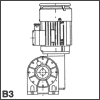
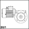
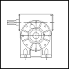
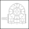
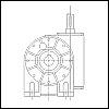
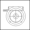
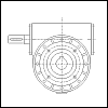
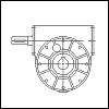
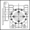
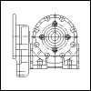
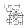
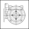
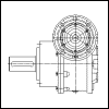
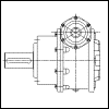
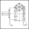
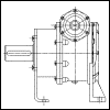
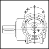
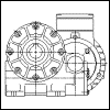
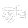
Dimensional drawings
Measurements for the various basic versions. Worm gear reducers can also be supplied with special measurements.
|
|
|
|
|
|
|
|
|
|
|
|
|
|
|
|
|

|

|

|

|

|

|

|

|

|

|

|

|

|

|

|

|
|
|
|
|
|
|
|
|
Accessories
Under the customer request is possible to deliver following accessories:
| TYPE | A1 | A2 | C | Dh7 | D1 | L | L1 | L2 | F | P | R | DS | M1 | M2 | Kg | |
|---|---|---|---|---|---|---|---|---|---|---|---|---|---|---|---|---|
| DIN 332 | I | II | ||||||||||||||
| RT – MRT 30A | 62 | 94 | 2,5 | 14 | 20 | 30 | 94,5 | 127 | 5 | 20 | 2,5 | 20 | M5 | M5 | 0,12 | 0,16 |
| RT – MRT 40A | 80 | 132 | 10 | 19 | 23 | 40 | 130 | 177 | 6 | 32 | 3 | 25 | M6 | M6 | 0,3 | 0,4 |
| RT – MRT 50A | 97 | 158 | 5 | 24 | 28 | 50 | 152 | 213 | 8 | 40 | 3,5 | 34 | M8 | M8 | 0,55 | 0,75 |
| RT – MRT 60A | 118 | 185 | 5 | 25 | 30 | 60 | 183 | 250 | 8 | 50 | 3,5 | 34 | M10 | M8 | 0,7 | 0,9 |
| RT – MRT 70A | 119 | 191 | 10 | 28 | 35 | 60 | 189 | 256 | 8 | 50 | 3,5 | 34 | M10 | M8 | 0,9 | 1,25 |
| RT – MRT 80A | 138 | 205 | 5 | 35 | 40 | 60 | 203 | 270 | 10 | 50 | 4 | 45 | M12 | M8 | 1,5 | 2 |
| RT – MRT 100A | 150 | 234 | 10 | 40 | 46 | 80 | 240 | 324 | 12 | 70 | 5 | 53 | M16 | M12 | 2,4 | 3,2 |
| RT – MRT 120A | 170 | 264 | 10 | 45 | 52 | 90 | 270 | 364 | 14 | 80 | 5 | 53 | M16 | M12 | 3,4 | 4,6 |
| RT – MRT 150A | 218 | 323 | 10 | 55 | 62 | 100 | 328 | 433 | 16 | 90 | 6 | 68 | M20 | M16 | 6,1 | 8,1 |
| RT – MRT 180A | 262 | 377 | 10 | 60 | 68 | 110 | 382 | 497 | 18 | 100 | 6 | 78 | M20 | M16 | 8,9 | 12 |
| TYPE | A1 | A2 | C | Dh7 | D1 | L | L1 | L2 | F | P | R | DS | M1 | M2 | Kg | |
|---|---|---|---|---|---|---|---|---|---|---|---|---|---|---|---|---|
| DIN 332 | I | II | ||||||||||||||
| RT – MRT 30A | 61 | 95,5 | 2,5 | 14 | 20 | 30 | 94 | 128 | 5 | 20 | 2,5 | 20 | M5 | M5 | 0,12 | 0,16 |
| RT – MRT 40A | 80 | 132 | 10 | 19 | 23 | 40 | 125 | 182 | 6 | 32 | 3 | 25 | M6 | M6 | 0,3 | 0,4 |
| RT – MRT 50A | 97 | 158 | 10 | 24 | 28 | 50 | 152 | 218 | 8 | 40 | 3,5 | 34 | M8 | M8 | 0,55 | 0,75 |
| RT – MRT 60A | 118 | 185 | 5 | 25 | 30 | 60 | 183 | 250 | 8 | 50 | 3,5 | 34 | M10 | M8 | 0,7 | 0,9 |
| RT – MRT 70A | 120 | 191 | 10 | 28 | 35 | 60 | 185 | 261 | 8 | 50 | 3,5 | 34 | M10 | M8 | 0,9 | 1,25 |
| RT – MRT 80A | 138 | 205 | 5 | 35 | 40 | 60 | 203 | 270 | 10 | 50 | 4 | 45 | M12 | M8 | 1,5 | 2 |
| RT – MRT 100A | 150 | 242 | 10 | 40 | 46 | 80 | 240 | 332 | 12 | 70 | 5 | 53 | M16 | M12 | 2,4 | 3,2 |
| RT – MRT 120A | 170 | 272 | 10 | 45 | 52 | 90 | 270 | 372 | 14 | 80 | 5 | 53 | M16 | M12 | 3,4 | 4,6 |
| RT – MRT 150A | 218 | 330 | 10 | 55 | 62 | 100 | 328 | 440 | 16 | 90 | 6 | 68 | M20 | M16 | 6,1 | 8,1 |
| RT – MRT 180A | 262 | 377 | 10 | 60 | 68 | 110 | 382 | 497 | 18 | 100 | 6 | 78 | M20 | M16 | 8,9 | 12 |
| TYPE | A | B | C | D | E | F | G | H | J | Weight |
|---|---|---|---|---|---|---|---|---|---|---|
| Kg | ||||||||||
| RT – MRT 30A | 85 | 40 | 143 | 55 | 65 | 8 | 14 | 7 | 4 | 0,22 |
| RT – MRT 40A | 100 | 39 | 161 | 50 | 65 | 8 | 14 | 7 | 4 | 0,25 |
| RT – MRT 50A | 100 | 44 | 170 | 60 | 75 | 10 | 20 | 7 | 4 | 0,3 |
| RT – MRT 60A | 150 | 53 | 233 | 70 | 85 | 10 | 20 | 9 | 5 | 0,57 |
| RT – MRT 70A | 200 | 62,5 | 295 | 80 | 100 | 14 | 24 | 9 | 6 | 1,1 |
| RT – MRT 80A | 200 | 77,5 | 315 | 110 | 130 | 14 | 24 | 11 | 6 | 1,25 |
| RT – MRT 100A | 230 | 77,5 | 345 | 110 | 130 | 14 | 24 | 11 | 6 | 1,35 |
| RT – MRT 120A | 260 | 95 | 395 | 130 | 165 | 16 | 26 | 13 | 8 | 2,45 |
| RT – MRT 150A | 300 | 125 | 480 | 180 | 215 | 16 | 26 | 15 | 8 | 3,7 |
| RT – MRT 180A | 350 | 150 | 545 | 230 | 265 | 25 | 30 | 17 | 8 | 4 |
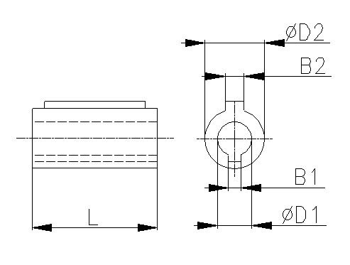
| ID | D1 | D2 | B1 | B2 | L |
|---|---|---|---|---|---|
| 1109 6356 | 9 | 11 | 3 | 4 | 20 |
| 1409 7156 | 9 | 14 | 3 | 5 | 30 |
| 1411 7163 | 11 | 14 | 4 | 5 | 23 |
| 1911 8063 | 11 | 19 | 4 | 6 | 40 |
| 2411 9063 | 11 | 24 | 4 | 8 | 50 |
| 1914 8071 | 14 | 19 | 5 | 6 | 30 |
| 2414 9071 | 14 | 24 | 5 | 8 | 50 |
| 2814 0071 | 14 | 28 | 5 | 8 | 60 |
| 2419 9080 | 19 | 24 | 6 | 8 | 40 |
| 2819 0080 | 19 | 28 | 6 | 8 | 60 |
| 3819 3280 | 19 | 38 | 6 | 10 | 80 |
| 2824 0090 | 24 | 28 | 8 | 8 | 50 |
| 3824 3290 | 24 | 38 | 8 | 10 | 80 |
| 4224 6090 | 24 | 42 | 8 | 12 | 110 |
| 3828 3200 | 28 | 38 | 8 | 10 | 80 |
| 4228 6000 | 28 | 42 | 8 | 12 | 110 |
| 4238 6032 | 38 | 42 | 10 | 12 | 80 |
Upon requirement of the client is possible to provide gear reducer RT and MRT on the output (or input) with:
- a suitable kind of shaft coupling for an aligning of a radial, axial and angular offsets of shafts
- slip clutch to limit transmitted torque
- eventually overrunning clutch
- combination of the flexible coupling with overload clutch
- combination of the flexible coupling with overrunning clutch.
Lublicants
RT/MRT gear units are lubricated by running the worm wheel or the worm in oil in combination with oil splashing. Under normal conditions a reliable operation as well as service life and efficiency of the gear units are secured. Gearboxes sizes 30 to 80 can be used at any mounting position. Gearboxes sizes 100 to 180 are suitable for mounting positions as shown in Table 4.1 Mounting Positions and Design due to positioning of the breathe plug. For any other mounting position please contact the manufacturers.
RT/MRT gear units are generally supplied filled for life – ÖMV PG 460EP is a synthetic oil enabling maintenance-free operation. Under normal conditions no oil needs to be changed during service life of the gearboxes. Should a different lubricant be required, e.g. due to more demanding conditions (higher operating temperature, high speed etc.), it must be established that oil additives do not affect bronze and/or oil seals in any way. It is recommended to use synthetic oils which guarantee high service life, stability and dynamic efficiency of the worm gears. When mineral oil is used, it must be changed in certain periods. In case grease is used as lubricant, reduction of heat dissipation, reduction of efficiency and reduced lubrication of all moving parts should be expected causing higher wear of the gear unit. Recommended equivalent lubricants are shown in the Tab. 19.1. The oil quantity per individual type and size of gear units is shown in the Table 19.2.
Table. 19.1 Equivalent Lubricants
| Ambient temperature | -10oC – +50oC | -30oC – +100oC | -40oC – +120oC | -10oC – +60oC | |
|---|---|---|---|---|---|
| Lubricant | Mineral oil | Synthetic oil | Synthetic grease | ||
| Type of load | normal | high | normal and high | normal and high | |
| OMV | Öle HST 320 EP | Öle HST 460 EP | PG 460 EP | PG 220 EP | Duraplex EP 00 |
| Agip | Blasia 320 | Blasia 460 | Blasia S | – | – |
| Aral | Degol BG 320 | Degol BG 460 | Degol GS 220 | Degol PAS 230 | Aralub BAB EP |
| Castrol | Alpha SP 320 | Alpha SP 460 | Alpha SH 220 | – | Alphagel |
| ESSO | Spartan EP 320 | Spartan EP 460 | – | – | Grease S420 |
| Kluber | Lamora 320 | Lamora 460 | Syntheso HT220 | Syntheso HT220 | Strugtovis P Liquid |
| Mobil | Mobilgear 632 | Mobilgear 634 | Glycoil 30 | – | Glycoil Grease 00 |
| Shell | Omala EP 320 | Omala EP 460 | Tivela Oil WB | Omala HD 320 | Tivela GL 00 |
| Optimol | Optigear BM 320 | Optigear BM 460 | Optiflex A 220 | – | Longtime PD 00 |
| Total | Carter EP 320 | Carter EP 460 | – | – | – |
| Paramo | Paramol CLP 320 | Paramol CLP 460 | – | – | – |
All gear units are supplied filled for life as standard.
Table. 19.2 Lubricant Fill
| Type |
Oil [l] |
|---|---|
| (M)RT 30A | 0,04 |
| (M)RT 40A | 0,13 |
| (M)RT 50A | 0,21 |
| (M)RT 60A | 0,36 |
| (M)RT 70A | 0,46 |
| (M)RT 80A | 0,7 |
| (M)RT 100A | 1,6 |
| (M)RT 120A | 2,2 |
| (M)RT 150A | 4 |
| (M)RT 180A | 7 |
| MRP 40A | 0,13+0,05 |
| MRP 50A | 0,21+0,05 |
| MRP 60A | 0,36+0,15 |
| MRP 70A | 0,46+0,20 |
| MRP 80A | 0,70+0,20 |
| MRP 100A | 1,6+0,3 |
| MRP 120A | 2,2+0,4 |
| MRP 150A | 4+0,3 |
| MRP 180A | 7,0+0,3 |
Storage, putting into the operation and maintenance
Storage
If the worm gear boxes are stored for longer periods of time or are not used, It Is necessary to take certain measures. All untreated metals need to be conserved in order to avoid corrosion. The choice of conservation depends on the environmental conditions. Storage should take place In a dust, moisture and vibration free environment to as great an extent as possible. If the reducers are fitted with a filling/ventilation plug, the reducer needs to be completely filled with oil, and the ventilation plug has to be sealed. It is recommended that the reducers are run for a few revolutions once every 3 – 4 months.
Instalation
The following aspects are important when installing a worm gear reducer:
- avoid external vibrations and high ambient temperatures
- an elastic coupling should be given preference for jolting loads
- shafts and couplings must be installed in line and according to the assembly instructions
- the worm gear reducer must be mounted on a level (machined) surface. If mounting is carried out directly on to the shaft to be driven, the entire construction process must be carried out in such a way that the reaction torque is sufficiently taken up
- all parts to be mounted on to the infeed shaft must be drawn using the tapped hole in the shaft on the reducer shaft in order to prevent damage being caused to the bearings
- mounting surtaces of flanges and shafts need to be conserved before assembly in order to prevent oxidization
- if oil lubrication is used the reducer must be filled with a quantity of oil as indicated on the type plate, see Tab. 19.2.
- if the reducer is not used for longer period of time, the storage instructions must be adhered to
- after long term storage with a full oil filling, it is important to adjust the oil quantity and to refit the ventilation plug before putting the unit into operation
Maintenance
Because the worm gear reducers are provided as standard with a syntetic grease lubricant maintenance is not necessary. For worm gear reducers with a mineral oil lubricant it is necessary to change the oil – see Table 12.1. After running in with oil the reducer must be cleaned and given new oil.
Running in
During the period of the first about 400 hours it is recommended that the reducer is not nominally loaded, but that a start is made with 70% for the first hours after which the load can be gradually increased to the nominal load. The rise in temperature is higher during the running in period than afterwards.
Cleaning
Drain the oil at operating temperature. Rinse the worm gear reducer clean.
Filling with oil
Fill the reducer with the definitive oil quantity as indicated on the type plate see Tab. 19.2.
Table 12.1. Lubricating intervals [h]
| oil temperature oC | type of load | mineral oil | synthetic oil/grease |
|---|---|---|---|
| < 60 | continuous interrupted | 4000 6000 |
lifetime |
| > 60 | continuous interrupted | 2000 4000 |
lifetime |
Warning:
Synthetic and mineral lubricants can not be mixed together. Mixing the synthetic lubricants of differing manufacturers can also cause problems. If the type or brand of lubricant is changed the reducer must be cleaned out.
Shaft seals
The good running thus the life of shaft seals, is affected in a very remarkable way by the running temperature in the contact area, by potential chemical reactions occuring between the rubber compound and the lubricant, and by the saving status of the seal itself. The replacement of shaft seals becomes necessary when: the seals are damaged and does not work proper way.
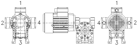
Spare parts
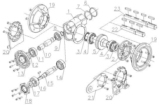
| 1 | Housing | 13 | Input flange |
|---|---|---|---|
| 2 | FT flange | 14 | Bearing |
| 3 | Oil seal | 15 | RT worm |
| 4 | Bearing | 16 | Bearing |
| 5 | Worm wheel | 17 | Oil seal |
| 6 | NBR cap | 18 | RT cap |
| 7 | Circlip | 19 | FF flange |
| 8 | Circlip | 20 | Foot |
| 9 | Bearing | 21 | Reaction arm |
| 10 | Worm gear | 22 | Output double-sided shaft – complete |
| 11 | Bearing | 23 | Output double-sided shaft – complete |
| 12 | Oil seal |
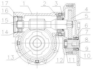
| 1 | Housing | 10 | Flange |
|---|---|---|---|
| 2 | Bearing | 11 | Bearing |
| 3 | Oil seal | 12 | Step gearing housing |
| 4 | Spur gear step | 13 | Worm wheel |
| 5 | Circlip | 14 | Bearing |
| 6 | Bearing | 15 | Circlip |
| 7 | Circlip | 16 | NBR cap |
| 8 | Pinion | 17 | Circlip |
| 9 | Oil seal |
Bearings and Seals
| TYPE | Motor | MRT | RT | ||||
|---|---|---|---|---|---|---|---|
| Bearing 4 | Bearing 7 | Oil gasket 2 | Bearing 4A | Bearing 7A | Oil gasket 2A | ||
| 30A | 56; 63 | HK 2016 | 6300 | 20x28x7 | 6201 | 6300 | 12x32x7 |
| 20x26x16 | 10x35x11 | 12x32x10 | 10x35x11 | ||||
| 40A | 63 | 6004 | 6302 | 20x35x7 | 6302 | 6302 | 15x26x7 |
| 20x42x12 | 15x42x13 | 15x42x13 | 15x42x13 | ||||
| 71 | 61905 | 6302 | 25x35x7 | ||||
| 25x42x9 | 15x42x13 | ||||||
| 50A | 63; 71 | 6205 | 6304 | 25x40x7 | 30304 | 30304 | 17x35x7 |
| 25x52x15 | 20x52x15 | 20x52x15 | 20x52x15 | ||||
| 80 | 61906 | 6304 | 30x40x7 | ||||
| 30x47x9 | 20x52x15 | ||||||
| 51107 | 30304 | 30x40x7 | |||||
| 35x37x12 | 20x52x15 | ||||||
| 60A | 71; 80 | 32006 | 30205 | 30x47x7 | 30206 | 30205 | 28×40-7 |
| 30x55x17 | 25x52x15 | 30x62x16 | 25x52x13 | ||||
| 90 | 61907 | 6304 | 35x47x7 | ||||
| 35x55x10 | 25x52x15 | ||||||
| 51107 | 30205 | 35x47x7 | |||||
| 35x52x12 | 25x52x15 | ||||||
| 70A | 71; 80 | 32006 | 30205 | 30x47x7 | 30206 | 30205 | 28×40-7 |
| 30x55x17 | 25x52x15 | 30x62x16 | 25x52x13 | ||||
| 90 | 61907 | 6304 | 35x47x7 | ||||
| 35x55x10 | 25x52x15 | ||||||
| 51107 | 30205 | 35x47x7 | |||||
| 35x52x12 | 25x52x15 | ||||||
| 80A | 80; 90 | 30207 | 30306 | 35x55x7 | 30206 | 30205 | 30x55x7 |
| 35x72x17 | 30x62x16 | 25x52x13 | |||||
| 100 | 32008 | 30306 | 40x55x7 | ||||
| 40x69x19 | 30x72x19 | ||||||
| 100A | 80; 90; 100; 112 | 32208 | 31307 | 40x62x12 | 32208 | 31307 | 40x62x8 |
| 40x80x24,75 | 35x80x22,75 | 40x80x24,75 | 35x80x22,75 | ||||
| 120A | 80; 90; 100; 112 | 32208 | 31307 | 40x62x12 | 32208 | 31307 | 40x62x8 |
| 40x80x24,75 | 35x80x22,75 | 40x80x24,75 | 35x80x22,75 | ||||
| 150A | 100; 112; 132 | 32211 | 31309 | 55x80x10 | 31309 | 31309 | 45x75x8 |
| 55x100x22,75 | 45x100x27,75 | 45x100x27,75 | 45x100x27,75 | ||||
| 180A | 112; 132; 160 | 31312 | 31312 | 60x80x10 | 31312 | 31312 | 60x75x9 |
| 60x130x33,5 | 60x130x33,5 | 60x130x33,5 | 60x130x33,5 | ||||
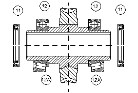
| TYP | 12 | 12A | 11 |
|---|---|---|---|
| RT – MRT 30A | 6005 | 7005 | |
| 25x47x12 | 25x47x12 | 25x40x7 | |
| RT – MRT 40A | 6006 | 32006 | |
| 30x55x13 | 30x55x17 | 30x47x7 | |
| RT – MRT 50A | 6007 | 32007 | |
| 35x62x14 | 35x62x18 | 35x50x7 | |
| RT – MRT 60A | 6008 | 32008 | |
| 40x68x15 | 40x68x19 | 40x55x7 | |
| RT – MRT 70A | 6009 | 32009 | |
| 45x75x16 | 45x75x20 | 45x60x8 | |
| RT – MRT 80A | 6010 | 32010 | |
| 50x80x16 | 50x80x20 | 50x65x8 | |
| RT – MRT 100A | 6011 | 32011 | |
| 55x90x18 | 55x90x23 | 55x72x10 | |
| RT – MRT 120A | 6013 | 32013 | |
| 65x100x18 | 65x100x23 | 65x85x12 | |
| RT – MRT 150A | 6216 | 30216 | |
| 80x140x26 | 80x140x28,25 | 80x100x10 | |
| RT – MRT 180A | 6218 | 32218 | |
| 90x160x30 | 90x160x42,5 | 90x110x12 |
Electromotors
This paragraph provides basic technical and dimensional data of three-phase squirrel cage asynchronous electric motors with frame sizes 56 to 160 supplied by Siemens. Any further details and/or technical information can be obtained from the manufacturers.
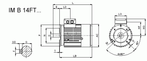
Mounting Positions of Electric Motors:
Terminal box on top as standard – pos. 1
If different terminal box position is required please specify in your order as special requirement.
Technical Data:
Mounting:
– flange mounted IM 3041 (IM B5), IM 3641 FT** (IM B14 FT**)
– foot & flange mounted IM 2081 (IM B35)
– all mounting to IEC 34-7 code I/II
Mounting dimension:
– in compliance with IEC 72 / DIN 42673
Protection:
– IP 55
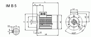
| Size | Flanged motors – dimensions in mm | ||||||||||||
|---|---|---|---|---|---|---|---|---|---|---|---|---|---|
| Dk6 | E | F | G | GD | AC | HF | HG | L | LB | LD | LG | LK | |
| 56 | 9 | 20 | 3 | 7,2 | 3 | 116 | 78,5 | 101 | 177 | 157 | 69,5 | 75 | 32 |
| 63 | 11 | 23 | 4 | 8,5 | 4 | 118 | 78,5 | 101 | 202 | 179 | 69,5 | 75 | 32 |
| 71 | 14 | 30 | 5 | 11 | 5 | 139 | 88,5 | 111 | 240 | 210 | 63,5 | 75 | 32 |
| 80 | 19 | 40 | 6 | 15,5 | 6 | 156,5 | 95,5 | 120 | 272,5 | 232,5 | 63,5 | 75 | 32 |
| 90 | 24 | 50 | 8 | 20 | 7 | 173,6 | 105,5 | 128 | 331 | 281 | 79 | 75 | 32 |
| 100 | 28 | 60 | 8 | 24 | 7 | 196 | 78 | 129 | 327,5 | 312,5 | 102 | 120 | 42 |
| 112 | 28 | 60 | 8 | 24 | 7 | 219,5 | 91 | 142 | 393 | 333 | 102 | 120 | 42 |
| 132S | 38 | 80 | 10 | 33 | 8 | 259 | 107 | 164 | 454 | 374 | 128,5 | 140 | 42 |
| 132M | 38 | 80 | 10 | 33 | 8 | 259 | 107 | 164 | 454 | 374 | 128,5 | 140 | 42 |
| 160M | 42 | 110 | 12 | 37 | 8 | 314 | 127 | 191 | 588 | 478 | 160,5 | 165 | 54 |
| 160L | 42 | 110 | 12 | 37 | 8 | 314 | 127 | 191 | 588 | 478 | 160,5 | 165 | 54 |
| Size | Flanged motors – dimensions in mm | ||||||||||||||||||
|---|---|---|---|---|---|---|---|---|---|---|---|---|---|---|---|---|---|---|---|
| Mounting IM B5 flange | Mounting IM B 14FT.. small flange | Mounting IM B 14FT.. bigger | |||||||||||||||||
| M | Nj6 | P | S | T | LA | M | Nj6 | P | S | T | M | Nj6 | P | S | T | ||||
| 56 | FF100 | 100 | 80 | 120 | 7 | 3 | 8 | FT65 | 65 | 50 | 80 | M5x16 | 2,5 | FT85 | 85 | 70 | 105 | M6x16 | 2,5 |
| 63 | FF115 | 115 | 95 | 140 | 10 | 3 | 8 | FT75 | 75 | 60 | 90 | M5x14 | 2,5 | FT100 | 100 | 80 | 120 | M6x16 | 3 |
| 71 | FF130 | 130 | 110 | 160 | 10 | 3,5 | 9 | FT85 | 85 | 70 | 105 | M6x16 | 2,5 | FT115 | 115 | 95 | 140 | M8x16 | 3 |
| 80 | FF165 | 165 | 130 | 200 | 12 | 3,5 | 10 | FT100 | 100 | 80 | 120 | M6x16 | 3 | FT130 | 130 | 110 | 160 | M8×16 | 3,5 |
| 90 | FF165 | 165 | 130 | 200 | 12 | 3,5 | 10 | FT115 | 115 | 95 | 140 | M8x21 | 3 | FT130 | 130 | 110 | 160 | M8×22 | 3,5 |
| 100 | FF215 | 215 | 180 | 250 | 14,5 | 4 | 11 | FT130 | 130 | 110 | 160 | M8×20 | 3,5 | FT165 | 160 | 130 | 200 | M10x20 | 3,5 |
| 112 | FF215 | 215 | 180 | 250 | 14,5 | 4 | 11 | FT130 | 130 | 110 | 160 | M8×20 | 3,5 | FT165 | 160 | 130 | 200 | M10×20 | 3,5 |
| 132S | FF265 | 265 | 230 | 300 | 14,5 | 4 | 12 | FT165 | 165 | 130 | 200 | M10×24 | 3,5 | – | – | – | – | – | – |
| 132M | FF265 | 265 | 230 | 300 | 14,5 | 4 | 12 | FT165 | 165 | 130 | 200 | M10×24 | 3,5 | – | – | – | – | – | – |
| 160M | FF300 | 300 | 250 | 350 | 18,5 | 5 | 13 | – | – | – | – | – | – | – | – | – | – | – | – |
| 160L | FF300 | 300 | 250 | 350 | 18,5 | 5 | 13 | – | – | – | – | – | – | – | – | – | – | – | – |
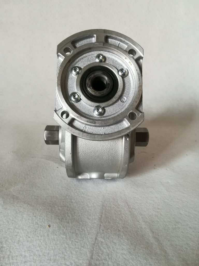
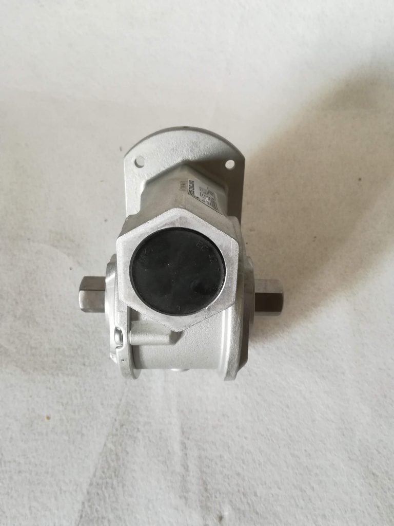
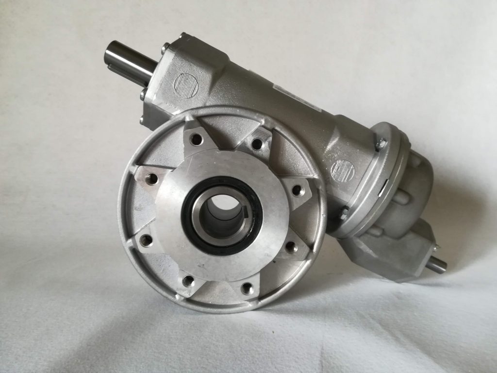
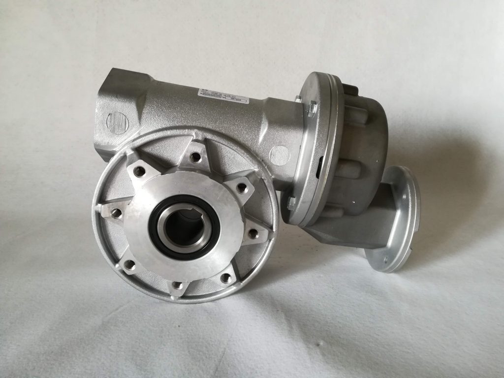
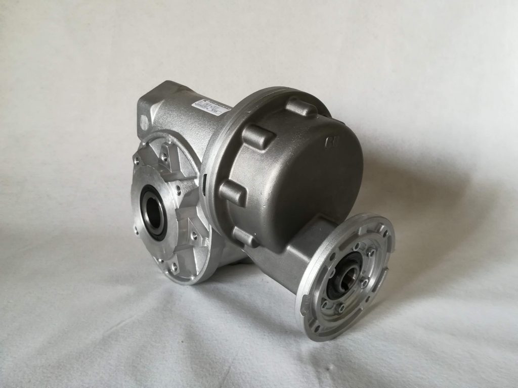
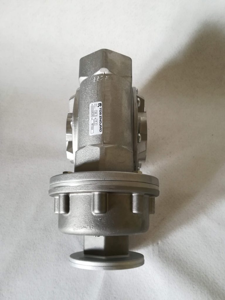
Photogallery
Worm gear reducers RT/MRT
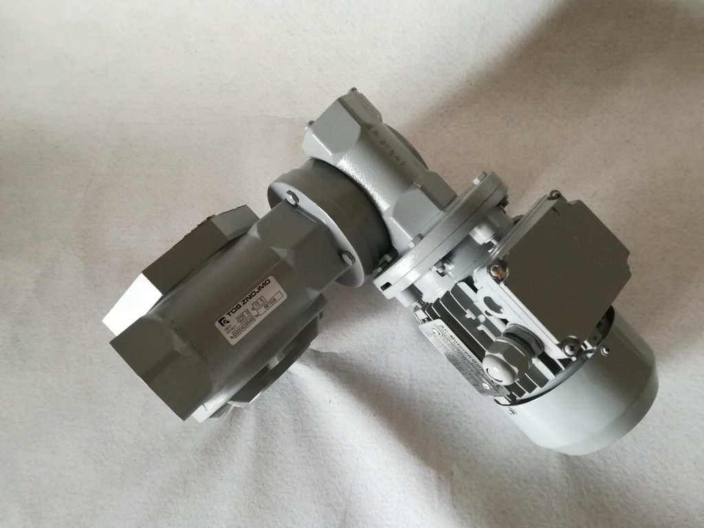
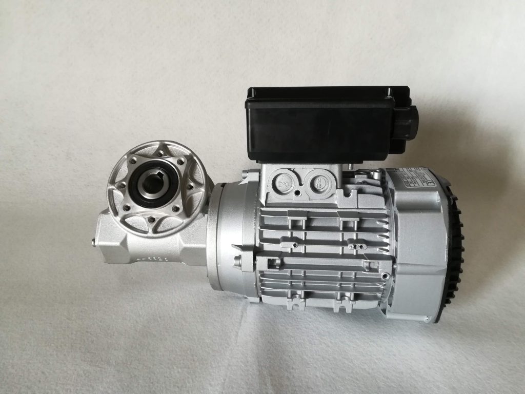

Worm gear RT with combination gearbox ATC

Výkresy a 3D modely
Převodovky MRT