Worm gear reducers MKT
Size: 63 – 75 – 90
Gear ratio: 7,5:1 – 100:1
Output: 0,18 – 4 kW
Torque: 50 – 550 Nm
General design
TOS Znojmo, Joint-Stock Co., a traditional manufacturer and supplier places a new generation of worm-gear units with high utility value and modern design on the market. The new conceptualisation of the gearbox made of aluminium alloy is characterised by universal design with high rigidity and low weight.
The ground worm with involute ZI contour is made of cemented hardened steel and together with a bronze wheel guarantee the torque transmission with high efficiency and minimum friction. Alternatively worm-gear units in stainless steel design can be delivered.
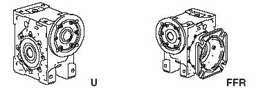
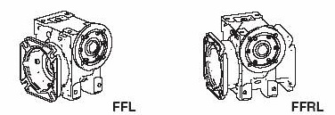
The basic bottom design with a small two-sided FT flange can be complemented with an FF flange adapter.
Identification
Basic designs:
KT.. Worm-gear unit with a shaft at input
MKT.. Worm-gear unit with an el. motor or a flange for the motor mounting
Identification chart
| Type | Size | Gear ratio | Design | Position | Motor |
|---|---|---|---|---|---|
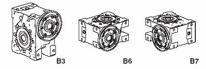
| KT with shaft at input | 63 | 7,5 | Basic design U | B3 | none |
| MKT with motor | 75 | 10 | Large flange right FFR | B6 | Table of power output data |
| 90 | 12,5 | Large flange left FFL | B7 | ||
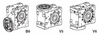
| 15 | Large flanges FFRL | B8 | |||
| 20 | V5 | ||||
| 25 | V6 | ||||
| 30 | |||||
| 40 | |||||
| 50 | |||||
| 60 | |||||
| 80 | |||||
| 100 |
Example:
| MKT | 63 | 30 | U | B3 | 71-4p 0,25kW |
MKT worm-gear unit with gear ratio 30 : 1 in the basic design U, working position B3 with el. motor 71-4p 9,25 kW.
Further data for the unit – e.g. size of motor and flange, varnish colour shade, grease type, stainless design or additional requirements.
Accessories – sliding-on shaft, reaction arm.
Service factors
To guarantee working safety with various load and operating conditions the gearbox (motor) type is specified with respect to the operating factor Sm. The table specifies the operating factor Sm values considering the kind of load, average working hours per day and the number of starts per an hour. These values apply to a gearbox driven by a usual motor. When a brake el. motor is used, it is necessary to multiply the operating factor Sm by coefficient 1,15.
Service factor Sf for the gear unit selected from the power output tables must be higher than the operating factor Sm.
Operating factor Sm
| Type of load | Starts per an hour | Average daily operation [hrs] | |||
|---|---|---|---|---|---|
| <2 | 2÷8 | 9÷16 | 17÷24 | ||
| normal start without surge, small accelerating weights (fans, gear pumps, assembly belts, transport screws, liquid mixers, filling and packing machines) |
<10 | 0,9 | 1,0 | 1,2 | 1,5 |
| >10 | 1,0 | 1,1 | 1,2 | 1,3 | |
| start with moderate surges, unstable operation, medium accelerating weight
(conveyor belts, elevators, hauling machines, blenders, woodworking and textile machines) |
<10 | 1,0 | 1,3 | 1,5 | 1,6 |
| 10÷50 | 1,2 | 1,4 | 1,7 | 1,9 | |
| 50÷100 | 1,3 | 1,6 | 2,0 | 2,1 | |
| 100÷200 | 1,5 | 1,9 | 2,3 | 2,4 | |
| unstable operation, strong surges, big accelerating weight (concrete mixers,
suction pumps, compressors, power hammers, rolling mills, heavy material containers, stamping machines, to and from motion machines) |
<10 | 1,2 | 1,5 | 1,8 | 2,0 |
| 10÷50 | 1,4 | 1,7 | 2,1 | 2,2 | |
| 50÷100 | 1,6 | 2,0 | 2,3 | 2,5 | |
| 100÷200 | 1,8 | 2,3 | 2,7 | 2,9 | |
Max. admissible radial load FR and axial load FA [N]
Fr1 – input shaft load, Fa2, Fr2 – output shaft load
| MKT 63 | MKT 75 | MKT 90 | ||||||||||
|---|---|---|---|---|---|---|---|---|---|---|---|---|
| n1=1400 ot | gear ratio | Fr1 | Fr2 | Fa2 | geart ratio | Fr1 | Fr2 | Fa2 | gear ratio | Fr1 | Fr2 | Fa2 |
| n2ot/min | i | (N) | (N) | (N) | i | (N) | (N) | (N) | i | (N) | (N) | (N) |
| 181 | 7,8 | 500 | 2400 | 480 | 7,8 | 700 | 2800 | 560 | 7,8 | 900 | 3100 | 620 |
| 145 | 9,7 | 550 | 2600 | 520 | 9,7 | 850 | 3100 | 620 | 9,7 | 1100 | 3400 | 680 |
| 111 | 12,7 | 600 | 2800 | 560 | 12,7 | 850 | 3300 | 660 | 12,7 | 1150 | 3600 | 720 |
| 90 | 15,5 | 600 | 3000 | 600 | 15,5 | 850 | 3500 | 700 | 15,5 | 1250 | 3900 | 780 |
| 72 | 19,5 | 650 | 3300 | 660 | 19,5 | 1000 | 3900 | 780 | 19,5 | 1250 | 4300 | 860 |
| 57 | 24,5 | 700 | 3500 | 700 | 24,5 | 1000 | 4200 | 840 | 24,5 | 1250 | 4600 | 920 |
| 47 | 30,0 | 700 | 3500 | 700 | 30,0 | 1000 | 4200 | 840 | 30,0 | 1250 | 4600 | 920 |
| 35 | 40,0 | 700 | 4100 | 820 | 40,0 | 1000 | 4900 | 980 | 40,0 | 1250 | 5400 | 1080 |
| 28 | 50,0 | 700 | 4400 | 880 | 50,0 | 1000 | 5200 | 1040 | 50,0 | 1250 | 5800 | 1160 |
| 23 | 60,0 | 700 | 4700 | 940 | 60,0 | 1000 | 5600 | 1120 | 60,0 | 1250 | 6200 | 1240 |
| 17,5 | 80,0 | 750 | 5200 | 1040 | 80,0 | 1000 | 6100 | 1220 | 80,0 | 1300 | 6800 | 1360 |
| 14 | 100,0 | 750 | 5600 | 1120 | 100,0 | 1000 | 6600 | 1320 | 100,0 | 1300 | 7300 | 1460 |
Dimensions of motor coupling holes and coordination of IEC motors with gear units
The size od motor and flange should be specified in the order of MKT worm-gear units supplied without motors.
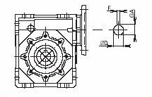
| IEC motor size |
Ø D E7 | F P9 | GA | MKT 63 | MKT 75 | MKT 90 |
|---|---|---|---|---|---|---|
| 71 | 14 | 5 | 16,3 | ♦ | ♦ | |
| 80 | 19 | 6 | 21,8 | ♦ | ♦ | ♦ |
| 90 | 24 | 8 | 27,3 | ♦ | ♦ | ♦ |
| 100 | 28 | 8 | 31,3 | ♦ | ♦ | |
| 112 | 28 | 8 | 31,3 | ♦ | ♦ |
Motor flanges of gear units and their coordination with gear units
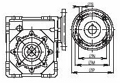
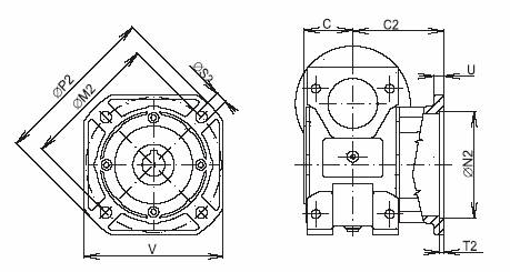
| Size | Ø M | Ø N H7 | Ø P | Ø S | MKT 63 | MKT 75 | MKT 90 |
|---|---|---|---|---|---|---|---|
| F 100 | 100 | 80 | 120 | 7 | ♦ | ||
| F 115 | 115 | 95 | 140 | 10 | ♦ | ♦ | ♦ |
| F 130 | 130 | 110 | 160 | 10 | ♦ | ♦ | ♦ |
| F 165 | 165 | 130 | 200 | 12 | ♦ | ♦ | ♦ |
| F 215 | 215 | 180 | 250 | 15 | ♦ | ♦ |
Table of max. values for MKT
| MKT 63 | 2 -pole motor, 2800 min-1 | MKT 63 | 4-pole motor, 1400 min-1 | MKT 63 | 6-pole motor, 900 min-1 | |||||||||
|---|---|---|---|---|---|---|---|---|---|---|---|---|---|---|
| i | n2 | Mk2 | P1 | Efficiency | i | n2 | Mk2 | P1 | Efficiency | i | n2 | Mk2 | P1 | Efficiency |
| – | [min-1] | [Nm] | [kW] | [%] | – | [min-1] | [Nm] | [kW] | [%] | – | [min-1] | [Nm] | [kW] | [%] |
| 7,8 | 361 | 115 | 4,71 | 92 | 7,8 | 181 | 137 | 2,90 | 91 | 7,8 | 116 | 153 | 2,09 | 89 |
| 9,7 | 290 | 120 | 4,01 | 91 | 9,7 | 145 | 143 | 2,47 | 89 | 9,7 | 93 | 160 | 1,79 | 87 |
| 12,7 | 221 | 114 | 2,94 | 90 | 12,7 | 111 | 136 | 1,83 | 87 | 12,7 | 71 | 152 | 1,33 | 85 |
| 15,5 | 181 | 123 | 2,67 | 87 | 15,5 | 90 | 146 | 1,65 | 85 | 15,5 | 58 | 164 | 1,21 | 82 |
| 19,5 | 144 | 116 | 2,03 | 86 | 19,5 | 72 | 138 | 1,27 | 83 | 19,5 | 46 | 155 | 0,94 | 79 |
| 24,5 | 114 | 111 | 1,59 | 84 | 24,5 | 57 | 132 | 1,00 | 80 | 24,5 | 37 | 148 | 0,74 | 77 |
| 30 | 93 | 134 | 1,70 | 77 | 30 | 47 | 160 | 1,07 | 74 | 30 | 30 | 179 | 0,79 | 72 |
| 40 | 70 | 129 | 1,24 | 76 | 40 | 35 | 153 | 0,80 | 71 | 40 | 23 | 171 | 0,60 | 67 |
| 50 | 56 | 122 | 0,98 | 73 | 28 | 145 | 0,64 | 67 | 50 | 18 | 162 | 0,49 | 63 | |
| 60 | 47 | 116 | 0,81 | 70 | 60 | 23 | 138 | 0,53 | 64 | 60 | 15 | 155 | 0,41 | 59 |
| 80 | 35 | 106 | 0,60 | 65 | 80 | 18 | 126 | 0,40 | 59 | 80 | 11 | 141 | 0,31 | 53 |
| 100 | 28 | 105 | 0,51 | 61 | 100 | 14 | 125 | 0,34 | 54 | 100 | 9 | 140 | 48 | |
| MKT 75 | 2-pole motor, 2800 min-1 | MKT 75 | 4-pole motor, 1400 min-1 | MKT 75 | 6-pole motor, 900 min-1 | |||||||||
|---|---|---|---|---|---|---|---|---|---|---|---|---|---|---|
| i | n2 | Mk2 | P1 | Efficiency | i | n2 | Mk2 | P1 | Efficiency | i | n2 | Mk2 | P1 | Efficiency |
| – | [min-1] | [Nm] | [kW] | [%] | – | [min-1] | [Nm] | [kW] | [%] | – | [min-1] | [Nm] | [kW] | [%] |
| 7,8 | 361 | 205 | 8,39 | 93 | 7,8 | 181 | 244 | 5,17 | 91 | 7,8 | 116 | 273 | 3,73 | 89 |
| 9,7 | 290 | 210 | 7,01 | 91 | 9,7 | 145 | 250 | 4,31 | 89 | 9,7 | 93 | 280 | 3,13 | 87 |
| 12,7 | 221 | 192 | 4,94 | 90 | 12,7 | 111 | 228 | 3,06 | 88 | 12,7 | 71 | 255 | 2,23 | 85 |
| 15,5 | 181 | 208 | 4,51 | 87 | 15,5 | 90 | 248 | 2,80 | 85 | 15,5 | 58 | 278 | 2,05 | 82 |
| 19,5 | 144 | 203 | 3,55 | 86 | 19,5 | 72 | 241 | 2,22 | 83 | 19,5 | 46 | 270 | 1,64 | 80 |
| 24,5 | 114 | 186 | 2,64 | 84 | 24,5 | 57 | 221 | 1,66 | 81 | 24,5 | 37 | 248 | 1,24 | 77 |
| 30 | 93 | 220 | 2,77 | 78 | 30 | 47 | 262 | 1,73 | 75 | 30 | 30 | 293 | 1,28 | 72 |
| 40 | 70 | 212 | 2,03 | 76 | 40 | 252 | 1,31 | 72 | 40 | 23 | 282 | 0,99 | 67 | |
| 50 | 56 | 195 | 1,54 | 74 | 50 | 28 | 232 | 1,00 | 69 | 50 | 18 | 260 | 0,77 | 64 |
| 60 | 47 | 187 | 1,28 | 71 | 60 | 23 | 222 | 0,84 | 66 | 60 | 15 | 249 | 0,65 | 60 |
| 80 | 35 | 163 | 0,90 | 66 | 80 | 18 | 194 | 0,60 | 60 | 80 | 11 | 217 | 0,47 | 54 |
| 100 | 28 | 151 | 0,71 | 62 | 100 | 14 | 180 | 0,48 | 57 | 100 | 9 | 202 | 0,38 | 50 |
| MKT 90 | 2-pole motor, 2800 min-1 | MKT 90 | 4-pole motor, 1400 min-1 | MKT 690 | 6-pole motor, 900 min-1 | |||||||||
|---|---|---|---|---|---|---|---|---|---|---|---|---|---|---|
| i | n2 | Mk2 | P1 | Efficiency | i | n2 | Mk2 | P1 | Efficiency | i | n2 | Mk2 | P1 | Efficiency |
| – | [min-1] | [Nm] | [kW] | [%] | – | [min-1] | [Nm] | [kW] | [%] | – | [min-1] | [Nm] | [kW] | [%] |
| 9,7 | 290 | 312 | 10,34 | 92 | 9,7 | 145 | 371 | 6,36 | 90 | 9,7 | 93 | 416 | 4,62 | 88 |
| 12,7 | 221 | 302 | 7,68 | 91 | 12,7 | 111 | 359 | 4,76 | 89 | 12,7 | 71 | 402 | 3,48 | 86 |
| 15,5 | 181 | 329 | 7,04 | 88 | 15,5 | 90 | 391 | 4,36 | 86 | 15,5 | 58 | 438 | 3,19 | 83 |
| 19,5 | 144 | 355 | 6,11 | 86 | 19,5 | 72 | 423 | 3,83 | 84 | 19,5 | 46 | 474 | 2,83 | 81 |
| 24,5 | 114 | 320 | 4,45 | 86 | 24,5 | 57 | 2,81 | 82 | 24,5 | 37 | 427 | 2,09 | 79 | |
| 30 | 93 | 408 | 5,03 | 79 | 30 | 47 | 486 | 3,15 | 76 | 30 | 30 | 544 | 2,33 | 73 |
| 40 | 70 | 383 | 3,60 | 78 | 40 | 35 | 456 | 2,32 | 73 | 40 | 23 | 511 | 1,76 | 68 |
| 50 | 56 | 328 | 2,53 | 76 | 50 | 28 | 390 | 1,65 | 70 | 50 | 18 | 437 | 1,26 | 65 |
| 60 | 47 | 308 | 2,04 | 74 | 60 | 23 | 367 | 1,34 | 68 | 60 | 15 | 411 | 1,04 | 62 |
| 80 | 35 | 267 | 1,40 | 70 | 80 | 18 | 318 | 0,94 | 63 | 80 | 11 | 356 | 0,74 | 57 |
| 100 | 28 | 244 | 1,09 | 66 | 100 | 14 | 290 | 0,73 | 59 | 100 | 9 | 235 | 0,58 | 52 |
Performance parameters
Input speed 1400 min -1
Vstupní otáčky 900 min -1
Vstupní otáčky 940 min -1
Lubricant
The worm-gear units are filled with PG 460 EP synthetic oil as standard.
| mineral oil | synthetic oil | synthetic grease | |||
|---|---|---|---|---|---|
| ambient temperature | -10oC – +50oC | -10oC – +50oC | -10oC – +80oC | -10oC – +60oC | |
| normal load | heavy load | normal and heavy load | |||
| ÖMV | Öle HST 320 EP | Öle HST 460 EP | PG 460 EP | PG 220 EP | |
| Shell | Omala EP 320 | Omala EP 460 | Tivela Oil WB | Omala HD 320 | Tivela GL 00 |
| Optimol | Longtime PD 00 | ||||
Table: Lubricant quantity
| Size | Oil quantity [l] |
|---|---|
| MKT 63 | 0,4 |
| MKT 75 | 0,6 |
| MKT 90 | 1,2 |
Sizes of worm-gear units
Basic design U
| Size | A | AB | B | b | b1 | BB | C | Ø DH7 | F | GA | H | H1 | H2 | I | J | K | L1 | Ø M | Ø N | S | T | m [kg] |
|---|---|---|---|---|---|---|---|---|---|---|---|---|---|---|---|---|---|---|---|---|---|---|
| MKT 63 | 85 | 109 | 100 | 50 | 80 | 144 | 56 | 25 | 8 | 28,3 | 174 | 72 | 102 | 63 | 8 | 9 | 95 | 95 | 80 | M8-14 | 3.0 | 6 |
| MKT 75 | 90 | 112 | 120 | 60 | 93 | 172 | 60 | 28 | 8 | 31,3 | 205 | 86 | 119 | 75 | 10 | 11 | 113 | 115 | 95 | M8-14 | 3.0 | 9 |
| MKT 90 | 100 | 130 | 140 | 70 | 102 | 206 | 70 | 35 | 10 | 38,3 | 238 | 103 | 135 | 90 | 11 | 13 | 130 | 130 | 110 | M10-18 | 3,5 | 13 |
Output shaft FF
| Size | C | C2 | M2 | Ø N2 H7 | Ø P2 | S2 | T2 | U | V | m [kg] |
|---|---|---|---|---|---|---|---|---|---|---|
| MKT 63 | 56 | 88 | 150 | 115 | 180 | 11 | 5 | 11 | 142 | 6,5 |
| MKT 75 | 60 | 111 | 165 | 130 | 200 | 14 | 5 | 12 | 170 | 10,0 |
| MKT 90 | 70 | 111 | 175 | 152 | 210 | 14 | 6 | 13 | 200 | 14,0 |
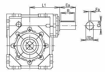
Shaft at inlet
| Size | Ø Da | Ea | Fa | Ga | R | L1 |
|---|---|---|---|---|---|---|
| MKT 63 | 19 | 40 | 6 | 21,5 | 40 | 95 |
| MKT 75 | 24 | 50 | 8 | 27,0 | 50 | 113 |
| MKT 90 | 24 | 50 | 8 | 27,0 | 50 | 129 |
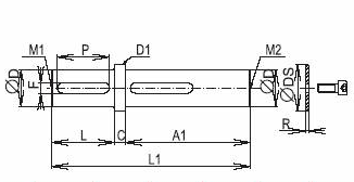
Single-sided shaft I
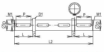
Double-sided shaft II
| Size | A1 | C | ø D h7 | ø D1 | L | L1 | L2 | F | P | R | DS | M1 | M2 | weight[kg] | |
|---|---|---|---|---|---|---|---|---|---|---|---|---|---|---|---|
| DIN 332 | I | II | |||||||||||||
| MKT 63 | 111 | 4 | 25 | 32 | 50 | 165 | 220 | 8 | 40 | 3.5 | 34 | M10 | M8 | 0.7 | 1.0 |
| MKT 75 | 119 | 4 | 28 | 35 | 60 | 183 | 248 | 8 | 50 | 3.5 | 34 | M10 | M8 | 0.9 | 1.3 |
| MKT 90 | 138 | 5 | 35 | 40 | 60 | 203 | 270 | 50 | 70 | 4.0 | 45 | M12 | M8 | 1.6 | 2.7 |
Photogallery

Výkresy a 3D modely
Převodovky MKT, velikost 90


