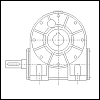
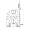
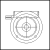
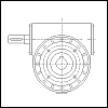
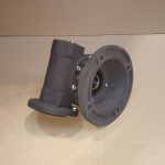
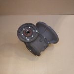
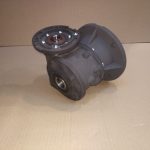
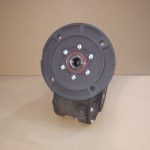
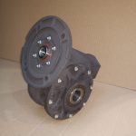
Worm gear reducers MRT..E
Gearboxes for advanced applications.
Size: 40, 50, 60, 70, 80, 90
Transmission ratio: „i“ = 5 – 100
Power: 0,09 – 7,5 kW
Torque: 9 – 691 Nm
General design
MRT..E are worm gearboxes for advanced applications.
MRT..Evolution offers longer service life, lower operating and maintenance costs, while maintaining the dimensions of the existing recognized MRT..A order.
Characteristic properties of worm-gear units:
Transfer of higher torque
Mk by 8% compared to the MRT..A order while maintaining the connection dimensions
Worm gear grinding for roughness to Ra0.4
for maximum efficiency of the worm gear
Bearings of selected prestigious brands
(SKF, FAG, TIMKEN) for maximum durability and loadability
Fully synthetic lubricant
forming a lifetime load
Metal cap
to capture the axial force in the screw worm gearboxes
Reinforced bronze wreath of worm wheel
to transmit higher torque
Shaft seal with high heat resistance
from the material FPM (VITON) on the screw worm gearboxes
Extended Warranty
24 months
A QR code tag
for easy identification
Guaranteed stock of selected transfers
for short delivery dates
On request, black anodized cabinet
for high resistance to the environment, abrasion resistance and pleasant aesthetic impression
Sales Specialists:
| Dominik Jelínek
Dominik_jelinek@tos-znojmo.cz +420 515 288 213 |
Lukáš Trojek
Lukas_trojek@tos-znojmo.cz +420 515 288 212 |
Selection
General
The wide range of ratios specified in the catalogue enables to solve any requirements resulting from the operation of various equipment. The following data are necessary to specify a suitable gear unit:
a) input and output speed determining the gear ratio i
b) required torque Mk, or input power P1
The data given in the tables 8.1 až 8.4, enable easy selection of a suitable gear unit. Should a non-standard unit be required please contact your distributors for the technical support.
Gear Ratio i
Gear ratio is a relation between input speed n1 [rpm] and output speed n2 [rpm].
n1
i = ——————— [-]
n2
Gear ratios from 5 to 100 are used at worm-gear units. The use of squirrel cage asynchronous motors is recommended to drive the equipment as their speed n1 [rpm] is almost constant even if under load. The following speed can be used for 50 Hz:
- 2 – pole motor n1=2800 rpm
- 4 – pole motor n1=1400 rpm
- 6 – pole motor n1=900 rpm
- 8 – pole motor n1=700 rpm
Two-pole motors are usually suitable for short-time operation.. After consultation with the manufacturer, these uses are also possible. Their use should be consulted with the manufacturers. When 60 Hz supply frequency is used the increase of the input as well as output speed by 20 % need to be taken into consideration.
Torque M2
The required torque Mk is determined by the load applied on the gear unit. It can be described as force F applied at certain distance of the arm r.
Mk[Nm] = F[N] x r[m]
The output torque M2 can be calculated from the following formula:
9550 x P1[kW] x  [%] x i
M2[Nm] = —————————————–
100 x n1[rpm]
The output torque M2 is greater than the desired torque. 2 need to be selected at a higher value than the required torque. Output torque related to individual gear ratios is specified in the Gear Unit Selection 8.4.
Input and Output Power P1 and P2
Motor input power can be calculated from the general relation between torque M and speed n :
M[Nm] x n[rpm]
P[kW] = —————————-
9550
The efficiency  , of a gear unit is given by the ratio of the output power P2 and the input power P1, see Table 8.1 to 8.3.
Mkrequired [Nm] x n2[rpm]
P1[kW] = —————————————————-
9550 x  [%]
[%]
TYPE IDENTIFICATION DIAGRAM
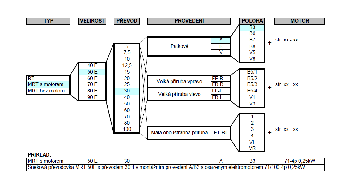
Nominal power
In operating conditions with a service factor Sm = 1 the reducers can be maximally loaded with capacities as shown in table 8.1., 22.1., 8.2. – 8.3. These tables show various ingoing revolutions, n1 [min-1], the maximum outgoing torques M2max [Nm] and the accompanying ingoing capacities P1[kW]. In exceptional cases can be used ingoing otáčky n1 = 2800 [min-1], but should be consulted with the manufacturer.
Combination of two worm gear reducers is a precondition for achieving very high ratio under keeping high compactibility. This design allows in the abstract to achieve ratio upto 10 000:1. From practical reasons are used ratios only upto 4 000:1.
Table 8.1. Table of Rated Data MRT
Performance parameters
Selection of a gear unit with electric motor we can make as a Table 8.4. Tables are lined up for a posibility posibility of an ideal gear unit size selection based on a requested electric motor input power. Requested ratio and output speed show appropriate torque M2 and service factor Sf. These values are in table stated for electric motors of 4 and 6 poles execution.
Table 8.4.1. Table of Performance Data of Gear Units MRT..E
Dimensional Drawings
Measurements for the various basic versions. Worm gear reducers can also be supplied with special measurements.
The installation dimensions of the MRT..E gearboxes are the same as the MRT..A series.
Accessories
Under the customer request is possible to deliver following accessories:
Převodovky RT a MRT je dle konkrétního požadavku zákazníka možno vybavit na výstupu (popř. na vstupu) vhodným typem hřídelové spojky pro vyrovnání radiálního, axiálního a úhlového přesazení hřídelů, prokluzovou spojkou pro omezení přenášeného kroutící momentu, popř. volnoběžkou, nebo i kombinací pružné spojky s prokluzovou a pružné spojky s volnoběžkou.
Lubricants
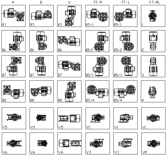
RT/MRT gear units are lubricated by running the worm wheel or the worm in oil in combination with oil splashing. Under normal conditions a reliable operation as well as service life and efficiency of the gear units are secured. Gearboxes sizes 30 to 80 can be used at any mounting position. Gearboxes sizes 100 to 180 are suitable for mounting positions as shown in Table 4.1 Mounting Positions and Design due to positioning of the breathe plug. For any other mounting position please contact the manufacturers.
RT/MRT gear units are generally supplied filled for life – ÖMV PG 460EP is a synthetic oil enabling maintenance-free operation. Under normal conditions no oil needs to be changed during service life of the gearboxes. Should a different lubricant be required, e.g. due to more demanding conditions (higher operating temperature, high speed etc.), it must be established that oil additives do not affect bronze and/or oil seals in any way. It is recommended to use synthetic oils which guarantee high service life, stability and dynamic efficiency of the worm gears. When mineral oil is used, it must be changed in certain periods. In case grease is used as lubricant, reduction of heat dissipation, reduction of efficiency and reduced lubrication of all moving parts should be expected causing higher wear of the gear unit. Recommended equivalent lubricants are shown in the Tab. 19.1. The oil quantity per individual type and size of gear units is shown in the Table 19.2.
Table. 19.1 Equivalent Lubricants
| Ambient temperature | -10oC – +50oC | -30oC – +100oC | -40oC – +120oC | -10oC – +60oC | |
|---|---|---|---|---|---|
| Lubricant | Mineral oil | Synthetic oil | Synthetic grease | ||
| Type of load | normal | high | normal and high | normal and high | |
| OMV | Öle HST 320 EP | Öle HST 460 EP | PG 460 EP | PG 220 EP | Duraplex EP 00 |
| Agip | Blasia 320 | Blasia 460 | Blasia S | – | – |
| Aral | Degol BG 320 | Degol BG 460 | Degol GS 220 | Degol PAS 230 | Aralub BAB EP |
| Castrol | Alpha SP 320 | Alpha SP 460 | Alpha SH 220 | – | Alphagel |
| ESSO | Spartan EP 320 | Spartan EP 460 | – | – | Grease S420 |
| Kluber | Lamora 320 | Lamora 460 | Syntheso HT220 | Syntheso HT220 | Strugtovis P Liquid |
| Mobil | Mobilgear 632 | Mobilgear 634 | Glycoil 30 | – | Glycoil Grease 00 |
| Shell | Omala EP 320 | Omala EP 460 | Tivela Oil WB | Omala HD 320 | Tivela GL 00 |
| Optimol | Optigear BM 320 | Optigear BM 460 | Optiflex A 220 | – | Longtime PD 00 |
| Total | Carter EP 320 | Carter EP 460 | – | – | – |
| Paramo | Paramol CLP 320 | Paramol CLP 460 | – | – | – |
All gear units are supplied filled for life as standard.
Table. 19.2 Lubricant Fill
| Type |
Oil [l] |
|---|---|
| (M)RT 40E | 0,13 |
| (M)RT 50E | 0,21 |
| (M)RT 60E | 0,36 |
| (M)RT 70E | 0,46 |
| (M)RT 80E | 0,7 |
| (M)RT 90E | 1,1 |
Storage, putting into the operation and maintenance
Storage
If the worm gear boxes are stored for longer periods of time or are not used, It Is necessary to take certain measures. All untreated metals need to be conserved in order to avoid corrosion. The choice of conservation depends on the environmental conditions. Storage should take place In a dust, moisture and vibration free environment to as great an extent as possible. If the reducers are fitted with a filling/ventilation plug, the reducer needs to be completely filled with oil, and the ventilation plug has to be sealed. It is recommended that the reducers are run for a few revolutions once every 3 – 4 months.
Instalation
The following aspects are important when installing a worm gear reducer:
- avoid external vibrations and high ambient temperatures
- an elastic coupling should be given preference for jolting loads
- shafts and couplings must be installed in line and according to the assembly instructions
- the worm gear reducer must be mounted on a level (machined) surface. If mounting is carried out directly on to the shaft to be driven, the entire construction process must be carried out in such a way that the reaction torque is sufficiently taken up
- all parts to be mounted on to the infeed shaft must be drawn using the tapped hole in the shaft on the reducer shaft in order to prevent damage being caused to the bearings
- mounting surtaces of flanges and shafts need to be conserved before assembly in order to prevent oxidization
- if oil lubrication is used the reducer must be filled with a quantity of oil as indicated on the type plate, see Tab. 19.2.
- if the reducer is not used for longer period of time, the storage instructions must be adhered to
- after long term storage with a full oil filling, it is important to adjust the oil quantity and to refit the ventilation plug before putting the unit into operation
Maintenance
Because the worm gear reducers are provided as standard with a syntetic grease lubricant maintenance is not necessary. For worm gear reducers with a mineral oil lubricant it is necessary to change the oil – see Table 12.1. After running in with oil the reducer must be cleaned and given new oil.
Running in
During the period of the first about 400 hours it is recommended that the reducer is not nominally loaded, but that a start is made with 70% for the first hours after which the load can be gradually increased to the nominal load. The rise in temperature is higher during the running in period than afterwards.
Cleaning
Drain the oil at operating temperature. Rinse the worm gear reducer clean.
Filling with oil
Fill the reducer with the definitive oil quantity as indicated on the type plate see Tab. 19.2.
Tabulka 12.1. Mazací intervaly [h]
| oil temperature oC | type of load | mineral oil | oil/ grease |
|---|---|---|---|
| < 60 | continuous interrupted |
4000 6000 |
lifetime |
| > 60 | continuous interrupted |
2000 4000 |
lifetime |
Warning:
Synthetic and mineral lubricants can not be mixed together. Mixing the synthetic lubricants of differing manufacturers can also cause problems. If the type or brand of lubricant is changed the reducer must be cleaned out.
Shaft seals
The good running thus the life of shaft seals, is affected in a very remarkable way by the running temperature in the contact area, by potential chemical reactions occuring between the rubber compound and the lubricant, and by the saving status of the seal itself. The replacement of shaft seals becomes necessary when: the seals are damaged and does not work proper way.
Spare parts
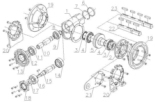
| 1 | Housing | 13 | Input flange |
|---|---|---|---|
| 2 | FT flange | 14 | Bearing |
| 3 | Oil seal | 15 | RT worm |
| 4 | Bearing | 16 | Bearing |
| 5 | Worm wheel | 17 | Oil seal |
| 6 | NBR cap | 18 | RT cap |
| 7 | Circlip | 19 | FF flange |
| 8 | Circlip | 20 | Foot |
| 9 | Bearing | 21 | Reaction arm |
| 10 | Worm gear | 22 | Output double-sided shaft – complete |
| 11 | Bearing | 23 | Output double-sided shaft – complete |
| 12 | Oil seal |
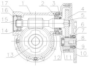
| 1 | Housing | 10 | Flange |
|---|---|---|---|
| 2 | Bearing | 11 | Bearing |
| 3 | Oil seal | 12 | Step gearing housing |
| 4 | Spur gear step | 13 | Worm wheel |
| 5 | Circlip | 14 | Bearing |
| 6 | Bearing | 15 | Circlip |
| 7 | Circlip | 16 | NBR cap |
| 8 | Pinion | 17 | Circlip |
| 9 | Oil seal |
Bearings and Seals
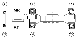
| TYPE | Motor | MRT | RT | ||||
|---|---|---|---|---|---|---|---|
| Bearing 4 | Bearing 7 | Oil gasket 2 | Bearing 4A | Bearing 7A | Oil gasket 2A | ||
| 30E | 56; 63 | HK 2016 | 6300 | 20x28x7 | 6201 | 6300 | 12x32x7 |
| 20x26x16 | 10x35x11 | 12x32x10 | 10x35x11 | ||||
| 40E | 63 | 6004 | 6302 | 20x35x7 | 6302 | 6302 | 15x26x7 |
| 20x42x12 | 15x42x13 | 15x42x13 | 15x42x13 | ||||
| 71 | 61905 | 6302 | 25x35x7 | ||||
| 25x42x9 | 15x42x13 | ||||||
| 50E | 63; 71 | 6205 | 6304 | 25x40x7 | 30304 | 30304 | 17x35x7 |
| 25x52x15 | 20x52x15 | 20x52x15 | 20x52x15 | ||||
| 80 | 61906 | 6304 | 30x40x7 | ||||
| 30x47x9 | 20x52x15 | ||||||
| 51107 | 30304 | 30x40x7 | |||||
| 35x37x12 | 20x52x15 | ||||||
| 60E | 71; 80 | 32006 | 30205 | 30x47x7 | 30206 | 30205 | 28×40-7 |
| 30x55x17 | 25x52x15 | 30x62x16 | 25x52x13 | ||||
| 90 | 61907 | 6304 | 35x47x7 | ||||
| 35x55x10 | 25x52x15 | ||||||
| 51107 | 30205 | 35x47x7 | |||||
| 35x52x12 | 25x52x15 | ||||||
| 70E | 71; 80 | 32006 | 30205 | 30x47x7 | 30206 | 30205 | 28×40-7 |
| 30x55x17 | 25x52x15 | 30x62x16 | 25x52x13 | ||||
| 90 | 61907 | 6304 | 35x47x7 | ||||
| 35x55x10 | 25x52x15 | ||||||
| 51107 | 30205 | 35x47x7 | |||||
| 35x52x12 | 25x52x15 | ||||||
| 80E | 80; 90 | 30207 | 30306 | 35x55x7 | 30206 | 30205 | 30x55x7 |
| 35x72x17 | 30x62x16 | 25x52x13 | |||||
| 100 | 32008 | 30306 | 40x55x7 | ||||
| 40x69x19 | 30x72x19 | ||||||
| 100E | 80; 90; 100; 112 | 32208 | 31307 | 40x62x12 | 32208 | 31307 | 40x62x8 |
| 40x80x24,75 | 35x80x22,75 | 40x80x24,75 | 35x80x22,75 | ||||
| 120E | 80; 90; 100; 112 | 32208 | 31307 | 40x62x12 | 32208 | 31307 | 40x62x8 |
| 40x80x24,75 | 35x80x22,75 | 40x80x24,75 | 35x80x22,75 | ||||
| 150E | 100; 112; 132 | 32211 | 31309 | 55x80x10 | 31309 | 31309 | 45x75x8 |
| 55x100x22,75 | 45x100x27,75 | 45x100x27,75 | 45x100x27,75 | ||||
| 180E | 112; 132; 160 | 31312 | 31312 | 60x80x10 | 31312 | 31312 | 60x75x9 |
| 60x130x33,5 | 60x130x33,5 | 60x130x33,5 | 60x130x33,5 | ||||
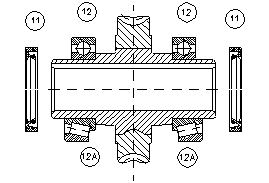
| TYP | 12 | 12A | 11 |
|---|---|---|---|
| RT – MRT 30E | 6005 | 7005 | |
| 25x47x12 | 25x47x12 | 25x40x7 | |
| RT – MRT 40E | 6006 | 32006 | |
| 30x55x13 | 30x55x17 | 30x47x7 | |
| RT – MRT 50E | 6007 | 32007 | |
| 35x62x14 | 35x62x18 | 35x50x7 | |
| RT – MRT 60E | 6008 | 32008 | |
| 40x68x15 | 40x68x19 | 40x55x7 | |
| RT – MRT 70E | 6009 | 32009 | |
| 45x75x16 | 45x75x20 | 45x60x8 | |
| RT – MRT 80E | 6010 | 32010 | |
| 50x80x16 | 50x80x20 | 50x65x8 | |
| RT – MRT 100E | 6011 | 32011 | |
| 55x90x18 | 55x90x23 | 55x72x10 | |
| RT – MRT 120E | 6013 | 32013 | |
| 65x100x18 | 65x100x23 | 65x85x12 | |
| RT – MRT 150E | 6216 | 30216 | |
| 80x140x26 | 80x140x28,25 | 80x100x10 | |
| RT – MRT 180E | 6218 | 32218 | |
| 90x160x30 | 90x160x42,5 | 90x110x12 |
Electric motors
This paragraph provides basic technical and dimensional data of three-phase squirrel cage asynchronous electric motors with frame sizes 56 to 160 supplied by Siemens. Any further details and/or technical information can be obtained from the manufacturers.
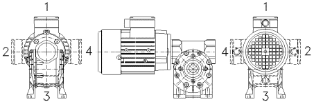
Mounting Positions of Electric Motors:
Terminal box on top as standard – pos. 1.
If different terminal box position is required please specify in your order as special requirement.
Technical Data:
Mounting:
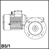
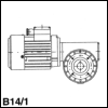
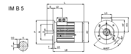
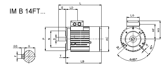
– flange mounted IM 3041 (IM B5), IM 3641 FT** (IM B14 FT**)
– foot & flange mounted IM 2081 (IM B35)
– all mounting to IEC 34-7 code I/II
Mounting dimension:
– in compliance with IEC 72 / DIN 42673
Protection:
– IP 55
Photogallery
Výkresy a 3D modely
Příslušenství MRT30
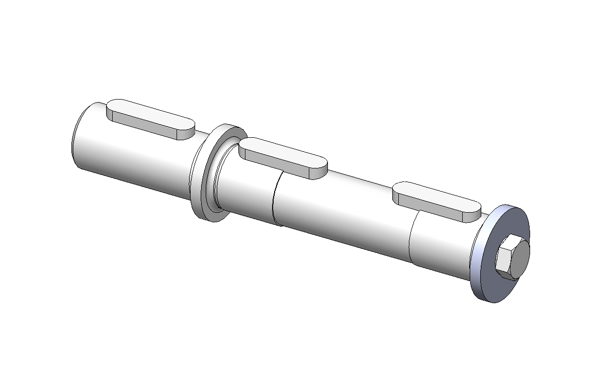
| Výstupní hřídel jednostranná | ||
|---|---|---|
| hridel_1-mrt30.dwb | hridel_1-mrt30.exe |
| hridel_1-mrt30.dwg | hridel_1-mrt30.step.zip | |
| hridel_1-mrt30.dxf | hridel_1-mrt30.sldprt | |
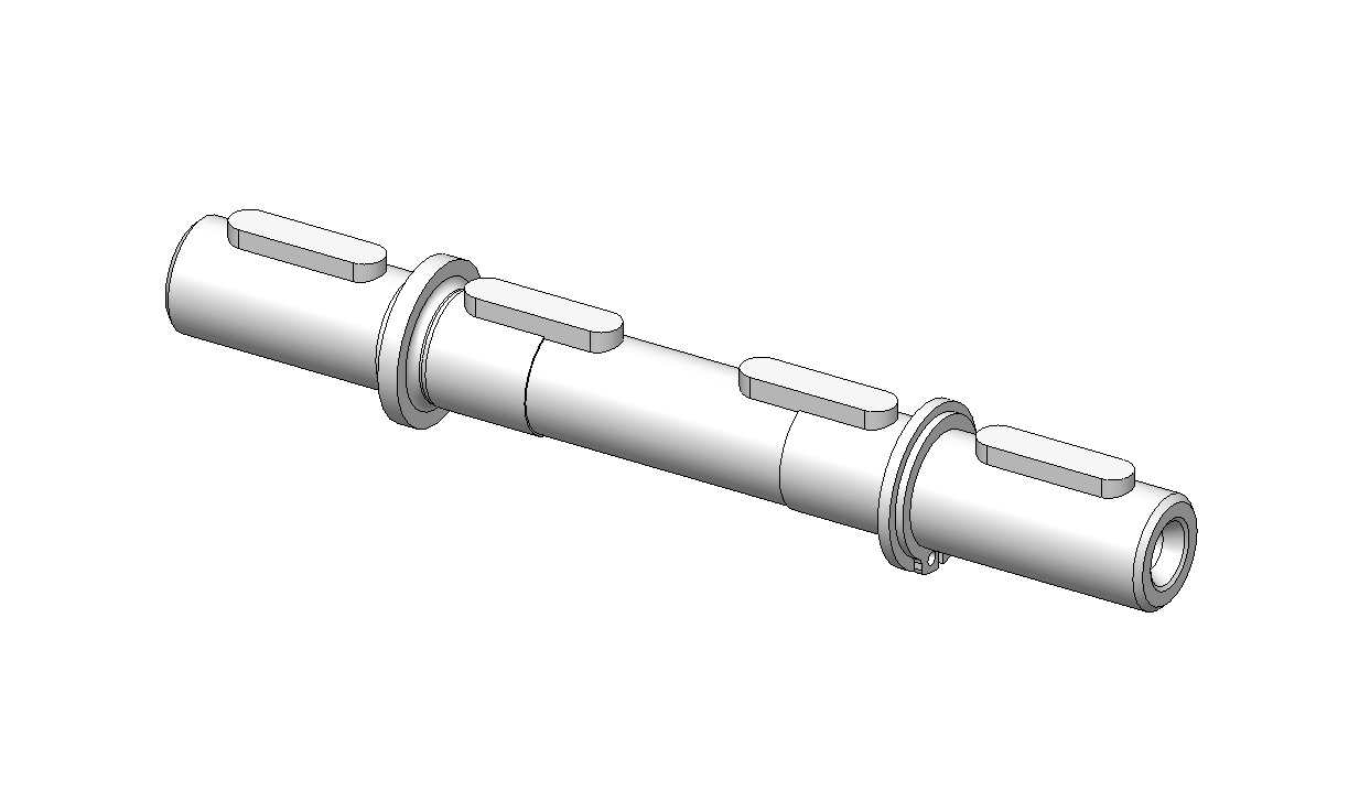
| Výstupní hřídel oboustranná | ||
| hridel_2-mrt30.dwb | hridel_2-mrt30.exe |
| hridel_2-mrt30.dwg | hridel_2-mrt30.step.zip | |
| hridel_2-mrt30.dxf | hridel_2-mrt30.sldprt | |
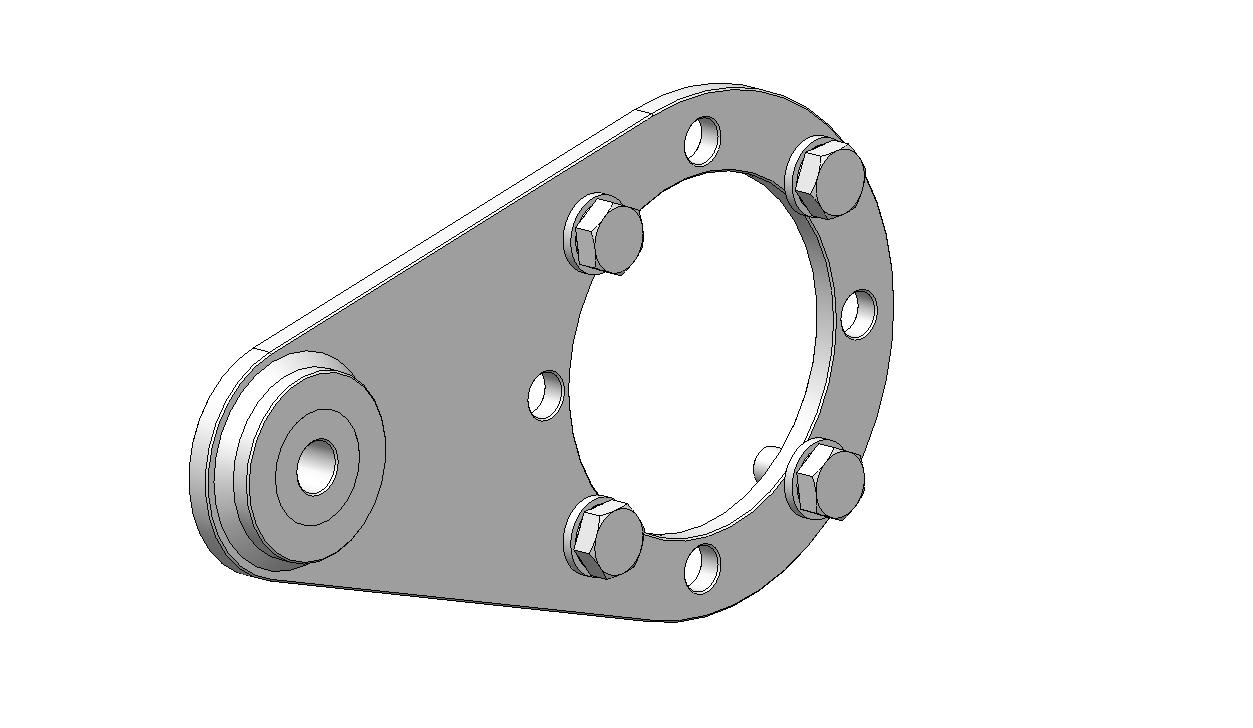
| Reakční rameno | ||
| r_rameno-mrt30.dwb | r_rameno-mrt30.exe |
| r_rameno-mrt30.dwg | r_rameno-mrt30.step.zip | |
| r_rameno-mrt30.dxf | r_rameno-mrt30.sldprt | |
The installation dimensions of the MRT..E gearboxes are the same as the MRT..A series.


