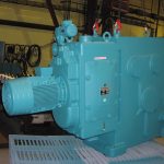
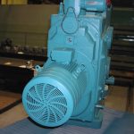
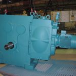
Variators
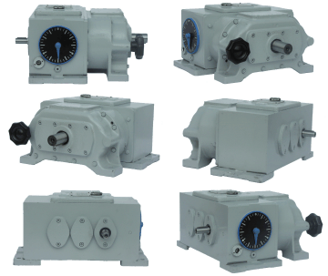
Type: VA – B
Size: 0 – 6
Control range: 1:3; 1:4,5; 1:6
Output: 0,85 – 21 kW
General design

The mechanical variable speed chain gear-boxes are one of the systems of infinitely variable speed gears assuming a dominant position in the driving technique for the transmission of little and mean outputs.
Owing to their properties, such as:
- the sufficiently large control range
- the suitable control characteristic
- the minimum drop of speed when loaded
- the minimum claims for maintenance
- the simple manipulation
the mechanical variable speed gear-boxes with plate-link chains range with the most demanded types.
Basic information
Conception
Variators in the basic design solve all requirements for infinitely variable gears from 0.85 to 21 kW outputs, with control range up to max. 1:6 and with optional output speed. All this is achieved by a purposeful division of the variable speed gearbox sizes and by a suitable connection with countershafts of unit-construction design on input and output sides.
Variable speed gear-boxes hold the speed at an optional value even at a variable load, as the power transmission is without slip. The advantage of these machines is the minimum requirements for space.
The output of the basic variable speed gear-box may be increased up to 55 kW by connecting a differential countershaft on the variable speed gear-box input side with the simultaneous reduction of the control range.
The output speed range may be increased, further, by connecting a satellite or movable layshaft on the variable speed gear-box output side.
Variable speed change
Basic elements of the infinitely variable speed change variable by the speed gear-boxes are two pairs of conical grooved disks and a plate-link chain. Grooved disks are fitted on driving and driven shafts and are axially movable on the same. Between these two pairs of disks there is directed and endless platelink chain which connects both pairs of disks – it changes the rotary motion of driving disks to the rectilinear one and on driven disks to the rotary motion again. The endless plate-link chain consists of a number of links which are mutually connected with pins; crosswise slidable plates are arranged inside the links.
The gear ratio may be changed so that disks of one pair are forced together, disks of the other pair are removed in dependence upon the first pair. In the pair of disks forced to each other, the chain gets moved to a larger diameter, in the opposite pair of disks, it gets moved to a smaller diameter. The required gear ratio is set up by means of two-armed levers being pivoted on a centric bolt.
Service factors
The values of outputs and torques stated in the tables apply to a normal single-shift operation and for not too frequent starting. In case of other operating conditions, an equivalent output must be ascertained for the determination of the variable speed gear-box size. To this effect the coefficients stated in the following table should be applied:
| Operating conditions | Coefficient | ||
|---|---|---|---|
| Number of starts in a hour |
10 | 1 | ks |
| above 10 | 1,3 | ||
| Number of operating hours |
up to 8 | 1 | kh |
| from 6 up 16 | 1,3 | ||
| from 16 up 24 | 1,5 | ||
| Character of load |
permanent | 1 | kz |
| intermittent | 1,3 | ||
| impact | 1,5 | ||
Determination of equivalent output
Example:
The determination of the variable speed gear-box size for driving a machine with following requirements:
| Infinitely variable speed control within …………… | 420-1250 | |
| Output Ns | at nmin ……………………… | approx. 0,75kW |
| at nmax …………………….. | approx. 1kW | |
| Number of startings ………………………………. | up to 10/hour | |
| Character of operation …………………………… | continuous | |
| Load ……………………………………………. | impact | |
Determination of equivalent output:
| Nmin | = Ns x ks x kh x kz |
|---|---|
| = 0,75 x 1 x 1,5 x 1,5 | |
| = 1,68 kW | |
| Nmax | = Ns x ks x kh x kz |
| = 1 x 1 x 1,5 x 1,5 | |
| = 2,25 kW |
On the basis of calculated values, there should be chosen „2“ variable speed gear-box with following values according to tables:
| Driving speed | n | = 720 ot/rpm |
|---|---|---|
| Output speed | nmin | = 415 ot/rpm |
| nmax | = 1245 ot/rpm | |
| Output | Nmin | = 1,9 kW |
| Nmax | = 2,6 kW |
Control range
The control range of the variable speed gear-box is understood the ratio of the minimum and maximum output speeds. The maximum control range variable speed gear-boxes is 1:6.
Typified control ranges with which the variable speed gear-boxes are currently delivered rate 1:3, 1:4.5 and 1:6. Upon the buyer’s wish, the variable speed gear-box may be adjusted for any control range up to 1:6.
Speed, output, torque of variable speed gear-box
The upper limit recommended for the variable speed gear-box output shaft speed is 1800 r.p.m. and the recommended lower limit is 200 r.p.m.
The typified variable speed gear-boxes (with driving speeds specified in tables) includes the optimum number of gear ratio kinds mutually tuned up with output. The values of output and torques are stated with respect to the efficiency of gears on the countershaft.
Every basic variable speed gear-box type has several variants according to the selected control way and position of the control system, according to the arrangement of input and output shafts and according to the cover position in vertical variable speed gear-boxes.
Technical specification of variators‘ regulating mechanism
The shaft ends are designed according to the ISO. Standards at k7 and provided with tapped pits according to Czechoslovak State Standard LSN 01 4917. Keys according to Czechoslovak State Standard ESN 02 2562. The axial height of shafts is within
tolerance of ± 1/600 H
The indicator and the control wheel must be situated on the same side of the variable speed gear-box. In the place of the control wheel there may be used the mechanical or electrical remote control.
The upper cover may be on A or B sides.
The variable speed gear-box should be situated so that the upper cover may be accessible for the reason of adjusting the variable speed gear-box or replacing the chain and oil. The mentioned oil quantity and mass are average values. A part view of the control part of the variable speed gear-box shows the design with pin control. The control by the regulating pin is not self-locking.
Supplied flange electromotors for sizes 0-6:
| Size | Transmission ratio | Regulating screw | Regulating pin | ||
|---|---|---|---|---|---|
| Output speed | Torque | Adjusting angle | Torque | ||
| 0 | 1:3 | 9 | 0,5 | 41° | 1 |
| 1:4,5 | 10,25 | 51° | |||
| 1:6 | 12 | 60° | |||
| 1 | 1:3 | 8,15 | 0,7 | 48° | 2 |
| 1:4,5 | 9,45 | 57° | |||
| 1:6 | 10,75 | 66° | |||
| 2 | 1:3 | 8,2 | 0,85 | 39° | 4 |
| 1:4,5 | 10 | 47° | |||
| 1:6 | 10,8 | 51° | |||
| 3 | 1:3 | 10,5 | 1 | 45° | 6 |
| 1:4,5 | 12,65 | 52° | |||
| 1:6 | 13,25 | 56° | |||
| 4 | 1:3 | 12,2 | 1,3 | 42° | 10 |
| 1:4,5 | 14,7 | 57° | |||
| 1:6 | 17,4 | 63° | |||
| 5 | 1:3 | 15,3 | 1,5 | 48° | 18 |
| 1:4,5 | 18,3 | 54° | |||
| 1:6 | 19,6 | 58° | |||
| 6 | 1:3 | 15 | 2 | 48° | 30 |
| 1:4,5 | 18,6 | 53° | |||
| 1:6 | 19,6 | 59° | |||
| Size | Motor | kW | V | Hz |
|---|---|---|---|---|
| „0“ | 4 AP 80-4 | 0,75 | 380/220 | 50 (60) |
| „1“ | 4 AP 90 L-4 | 1,5 | 380/220 | 50 (60) |
| „2“ | 4 AP 100 L-4 | 3 | 380/220 | 50 (60) |
| „3“ | 4 AP 112 M-4 | 5,6 (4) | 380/220 | 50 (60) |
| „4“ | 4 AP 132 M-4 | 7,5 | 380/220 | 50 (60) |
| „5“ | VC 160 L-4 | 15 | 380/220 | 50 (60) |
| „6“ | VC 180 L-4 | 22 | 380/220 | 50 (60) |
Designation
The table is intended for the precise determination of the type number. The variable speed drive proper is determined by five digits, the further two digits indicate the appertaining control. If there is concerned a combination of the variable speed drive with a gearbox, it is expressed according to the construction and size together with the clutch by other two digits. Designs of various positions of variable speed gear-boxes are stated in the table. If the conditions allow, it is the best to prefer two basic positions – horizontal position with feet or vertical position with feet. In case of vertical positions, the regulating screw is located in the upper part as far as possible. When the variable speed gear-box is built in a machine, it is necessary that it may be situated outside to facilitate access and inspection. The variable speed gear-box without countershaft only may be mounted on the flange.
a)Type: VA – variator
b) Size:
| code | 0 | 1 | 2 | 3 | 4 | 5 | 6 |
|---|---|---|---|---|---|---|---|
| power transmission [kW] | 0,85 | 1,7 | 3,4 | 5,6 | 8,7 | 14,8 | 21 |
c) Control range:
| code | 0 | 1 | 2 |
|---|---|---|---|
| control range | 1:3 | 1:4,5 | 1:6 |
d) Chain final tightener:
Letter „B“ after the second figure says the variator is provided by automatic chain final yokeless tightener.
e) Design of input:
| code | 1 | 2 | 3 | 4 | 5 |
|---|---|---|---|---|---|
 |
 |
 |
 |
 |
|
| Countershaft | simple | with single coun. | with double coun. | with triple coun. | with planet coun. |
| code | 6 | 7 | 8 | 9 | |
 |
 |
 |
 |
||
| Countershaft | with movable countershaft | with countershaft with bevel gears |
single worm countershaft |
double worm countershaft |
f) Drive execution:
| code | 0 | 1 | 2 | 3 | 4 | 8 |
|---|---|---|---|---|---|---|
 |
 |
 |
 |
 |
 |
|
| Execution | foot-type motor | flanged motor | motor on the box | reduction from motor | flanged motor, safety clutch |
differential gear |
g) Position:
| code | 1 | 2 | 3 | 4 |
|---|---|---|---|---|
 |
 |
 |
 |
|
| Position | horizontal | vertical | suspended vertical | vertical, fixed on the side |
| code | 5 | 6 | 7 | |
 |
 |
 |
||
| Position | suspensed horizontal | horizontal, fixed on the flange | vertical, fixed on the flange |
h) Regulation:
| code | 0 | 1 | 2 | 3 | 4 |
|---|---|---|---|---|---|
 |
 |
 |
 |
 |
|
| Regulation | manual with indicator | manual without indicator | by regulation pin | manual with special indicator | remote mechanical DM1 |
| code | 5 | 6 | 7 | 8 | |
 |
 |
 |
 |
||
| Regulation | remote mechanical DM2 | remote mechanical DM3 | electrical remote horizontally |
electrical remote vertically |
i) Location of Regulation:
| code | 0 | 1 | 2 | 3 | 4 |
|---|---|---|---|---|---|
 |
 |
 |
 |
 |
|
| Location of regulation | regulating screw up | regulating screw down | regulating screw on the left | regulating screw on the right | regulating pin up |
| code | 5 | 6 | 7 | 8 | 9 |
 |
 |
 |
 |
 |
|
| Location of regulation | regulating pin on the left | regulating pin on the right | regulating pin up with indicator | reg. pin on the left with indicator | reg. pin on the right with indicator |
Example of type number determination
A variable speed gear-box for transmission of 4 kW output with the control range of 1:4.5. Driving speed of 830 r.p.m., output speed of 177 to 796 r.p.m. Driven by a foot-type electric motor situated off the variable speed gear-box – by means of V-belts. Horizontal type of the variable speed gear-box. Hand control with a speed indicator. The regulating screw is situated on the left (when looked at from the output of the variable speed gear-box shaft).
| Variable speed gear-box for 4 kW transmission | first digit | 3 |
|---|---|---|
| Control range 1:4.5 – gear ratio | second digit | 1 |
| Output speed 177 to 796 r.p.m. at driving speed 830 r.p.m. – this a variable speed gear box witha single countershaft |
third digit | 2 |
| Driven by a foot-type motor | fourth digit | 0 |
| Horizontal type | fifth digit | 1 |
| Hand control with indicator | sixth digit | 0 |
| Regulating screw on the left | seventh digit | 2 |
| The variable speed gear-box type is then: |
|
Foot-type motors are not included in the delivery subject matter.
Instructions for ordering
In order that we may deliver a variable speed gear-box a correct design according to your choice, we ask you kindly to state technical data according to following instructions in your order. As far as all your requests are not contained in the instructions, kindly let us have the same or send us a diagrammatic sketch.
Technical parameters
 |
| simple |
 |
| with single countershaft |
 |
| with double countershaft |
 |
| with triple counteshaft |
Dimensional drawings
 |
| VA**B1*1-** |
|---|
| simple |
 |
| VA**B2*1-** |
|---|
| with single countershaft |
 |
| VA**B3**-** |
|---|
| with double countershaft |
 |
| VA**B4**-** |
|---|
| with triple countershaft |
 |
| VA**B1*2-** |
|---|
| simple |
 |
| VA**B2*2-** |
|---|
| with single countershaft |
Storage, putting into the operation and maintenance
Plate-link chains
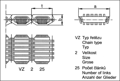
The plate-link chains are attached to the appertaining size of the variable speed gear-box and to the given control range in the table. In the type mark of the chain, the first digit indicates the basic chain size, the following double-digit number indicates the number of links. In the order of spare chains for variable speed gear-boxes, it is necessary to state the type mark of the variable speed gear-box which is shown on the orientation plate. These plate-link chains may be used even in some variable speed gear-boxes from other producers. In the order of chains for these variable speed gear-boxes, it is necessary to state the type and control range of the variable speed gear-box (e.g. AB 2 x 1:3).
Automatic chain final tightener
It is a special equipment of the variable speed gear-box which maintains the prescribed tightening of the plate-link chain within prescribed values for the chain service life automatically, without any operator’s manipulation.
The „L“ model chains will gradually replace the „V“, „VZ“ chains. The comparing table of models „L“ and „V“, „VZ“.
| Plate link chains | ||||
|---|---|---|---|---|
| V, VZ | L | |||
| V | 025 | A | L | 030 |
| V | 026 | A | L | 031 |
| VZ | 225 | A | L | 231 |
| VZ | 226 | A | L | 232 |
| VZ | 229 | A | L | 236 |
| VZ | 326 | A | L | 329 |
| VZ | 327 | A | L | 330 |
| VZ | 333 | A | L | 337 |
| VZ | 334 | A | L | 338 |
| VZ | 335 | A | L | 339 |
| VZ | 433 | A | L | 436 |
| VZ | 434 | A | L | 437 |
| VZ | 539 | A | L | 543 |
| VZ | 540 | A | L | 544 |
| VZ | 541 | A | K | 545 |
| VZ | 636 | A | L | 640 |
| VZ | 637 | A | L | 641 |
| VZ | 638 | A | L | 642 |
Chain replacement
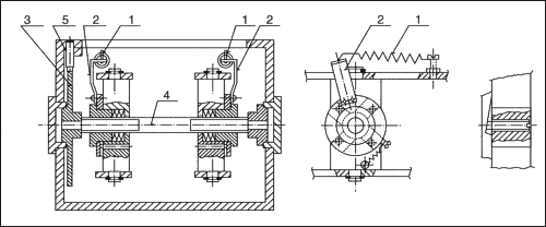
The gear ratio in the drive conversion unit is set to 1:1. The screw 5 must be loosened and the safety plate 3 must be turned till the chain is sufficiently loosened. The closing pin is taken out, the new chain is connected to the old one and by pulling out the old chain, the new ahain is drawn into the drive conversion unit. The old chain must be disconnected and the new one coupled by the closing pin. The tension springs 1, 1′ are released by taking them out from the holes in the stop levers 2, 2′ and the levers are shifted against the direction of the tension springs up to the stop into the starting position. The safety plate 3 must then be turned, till the stop levers 2, 2′ can be moved by 2-3 mm. The drive conversion unit must be turned gently at the same time as the safety plate is turned so as to correctly position the chain between the plates. The safety plate 3 must be secured by the screw 5 against turning, the tension springs 1, 1′ must be hung into the holes of the levers 2, 2′ and the drive conversion unit is prepared for operation.
Putting into operation of a variable speed gear-box with an automatic final tightener
Variable speed gear-boxes with automatic final tightener are supplied to the customer after being tested and run-in previously, so that they are serviceable after being filled with oil. If any manipulation in the variable speed gear-box mechanism is made for any reason, it will be necessary to check whether springs 1, 1′ are suspended and whether levers 2, 2′ are in their initial position before putting the variable speed gear-box into operation. Upon a request of the user, the automatic final tightening device can be mounted even in previously produced variable speed gear-boxes.
Lubrication
Variators are delivered including additional equipment without oil filling. The oil is poured into the horizontal and same vertical variators through venting screw on the main cover. Necessary oil quantity is mentioned on the production label of each variator. The kind of the oil filling for variator and additional equipment is mentioned here in the tabel. Replaceable kind has to be same quality and viscosity according to the enviroment temperature.
Table of recommended oils
| Enviroment temperature | Kind of oil | Viscosity |
|---|---|---|
| up to 35 °C | OT-K8 | min 11 mm2s-1 at 100 °C |
| max 76 mm2s-1 at 50 °C | ||
| over 35 °C | OT-K12 | min 15 mm2s-1 at 100 °C |
| max 114 mm2s-1 at 50 °C | ||
| over 45 °C | OT-K18 | min 19 mm2s-1 at 100 °C |
| max 175 mm2s-1 at 50 °C |
Oil exchange
The first oil exchange must be made after the first 500 operating hours, than after every 1000 operating hours. Used oil should be discharged warm. Cleaning is allowed only with oil-base drilling fluid, in no case use lamp-oil (kerosene) or other cleaning agents. Manufacturer’s guarantee is valid only under use of recommended oil or equal replacement.
Photogallery


